A very simple battery charger. DIY car battery charger Homemade rectifiers for charging the battery
The rectifier (Fig. 1) is assembled using a bridge circuit using four diodes D1 - D4 of type D305. The charging current is regulated. using a powerful transistor T1 connected according to a compound triode circuit. When the bias removed to the base of the triode from potentiometer R1 changes, the resistance of the collector-emitter circuit of the transistor changes. In this case, the charging current can be changed from 25 mA to 6 A with a voltage at the rectifier output from 1.5 to 14 V.
Resistor R2 at the rectifier output allows you to set the rectifier output voltage when the load is off. The transformer is assembled on a core with a cross section of 6 cm kvd. The primary winding is designed to be connected to a network with a voltage of 127 V (pins 1-2) or 220 V (1-3) and contains 350+325 turns of PEV 0.35 wire, the secondary winding - 45 turns of PEV 1.5 wire. Transistor T1 is installed on a metal radiator; the surface area of the radiator must be at least 350 cm2. The surface is taken into account on both sides of the plate with a thickness of at least 3 mm.
B. VASILIEV
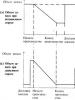
The diagram shown in Fig. 2 differs from the previous one in that in order to increase the maximum current to 10 o, transistors T1 and T2 are connected in parallel. The bias to the bases of the transistors, by changing which the charging current is regulated, is removed from the rectifier, made on diodes D5 - D6. When charging 6-volt batteries, the switch is set to position 1, 12-volt batteries - to position 2.

Fig.2
The transformer windings contain the following number of turns: la - 328 turns PEV 0.85; 1b - 233 turns PEV 0.63; II - 41+41 turns PEV 1.87; III - 7+7 turns PEV 0.63. Core - УШ35Х 55.
A. VARDASHKIN
(Radio 7 1966)
List of radioelements
| Designation | Type | Denomination | Quantity | Note | Shop | My notepad | |
|---|---|---|---|---|---|---|---|
| 25 mA to 6 A | |||||||
| T1 | Bipolar transistor | P210 | 1 | To notepad | |||
| T2 | Bipolar transistor | P201 | 1 | To notepad | |||
| D1-D4 | Diode | D305 | 4 | To notepad | |||
| R1 | Variable resistor | 1 kOhm | 1 | To notepad | |||
| R2 | Resistor | 1 kOhm | 1 | To notepad | |||
| Tr1 | Transformer | 1 | To notepad | ||||
| Pr1 | Fuse | 5A | 1 | To notepad | |||
| Up to 10 A | |||||||
| T1,T2 | Bipolar transistor | P210 | 2 | To notepad | |||
| D1-D4 | Diode | D305 | 4 | To notepad | |||
| D5, D6 | Diode | D303 | 2 | To notepad | |||
| R1 | Variable resistor | 50 ohm | 1 | ||||
Sometimes it’s easier to buy than to make a device from scratch with your own hands. But not always. For example, consider 12 volt car chargers. On the one hand, it serves a rather expensive item - a car battery, which, if used incorrectly, can fail, and with noise and crackling noise. But on the other hand, looking at the scheme of cheap industrial memory devices, you just wonder what they charge money for? This question is especially true for the Polish-Chinese 6-12V charger with no identification marks on the box other than a modest inscription Prostownik. I don't know what this word means, but it sounds simple :)
The charger was brought in for repairs, and no one knew what happened to it. It just lay around in the garage for a long time and stopped working. We will conduct an external inspection.

Indeed, on the case there is only the most necessary thing - a 1 ampere mains fuse and a 220 V cord in the rear, and in front there is a 6-12 V switch button, a 10 ampere fuse-link and a 0-8 A dial ammeter. There are not even cable connection terminals.

We disassemble the body and remove the cover. Inside - the same holy simplicity :)

Apart from the transformer and diode bridge, not a single one is observed. At least they installed a minimal electrolytic capacitor for filtering...

For some reason the wires turned out to be disconnected from the scarf with the diode bridge. Alternatively, the output wires may have shorted, the diodes have overheated and the wires have become unsoldered.

With a sinking feeling, I checked the transformer for functionality, because this is the most valuable part of any charger, and if it fails, then buying a similar one will be very expensive. 20 volt 5-10 amp transformers cost at least $10.

Thank God the primary showed a resistance of 22 Ohms, and not infinity :) Now checking the diodes - everything is OK here too. All that remains is to solder the wires according to the standard charging rectifier circuit.

The scheme worked. Measurements showed an alternating voltage from the output of the transformer - 13.8 V, and after the rectifier - 13 V constant. Why so few? - you ask - this is not enough to charge the car battery. Because it is pulsating in nature, and the voltmeter shows the effective average value.
Battery problems are not that uncommon. To restore functionality, additional charging is necessary, but normal charging costs a lot of money, and it can be done from available “trash.” The most important thing is to find a transformer with the required characteristics, and making a charger for a car battery with your own hands takes just a couple of hours (if you have all the necessary parts).
The battery charging process must follow certain rules. Moreover, the charging process depends on the type of battery. Violations of these rules lead to a decrease in capacity and service life. Therefore, the parameters of a car battery charger are selected for each specific case. This opportunity is provided by a complex charger with adjustable parameters or purchased specifically for this battery. There is a more practical option - making a charger for a car battery with your own hands. To know what parameters should be, a little theory.
Types of battery chargers
Battery charging is the process of restoring used capacity. To do this, a voltage is supplied to the battery terminals that is slightly higher than the operating parameters of the battery. Can be served:
- D.C. The charging time is at least 10 hours, during this entire time a fixed current is supplied, the voltage varies from 13.8-14.4 V at the beginning of the process to 12.8 V at the very end. With this type, the charge accumulates gradually and lasts longer. The disadvantage of this method is that it is necessary to control the process and turn off the charger in time, since when overcharging the electrolyte may boil, which will significantly reduce its working life.
- Constant pressure. When charging with a constant voltage, the charger produces a voltage of 14.4 V all the time, and the current varies from large values in the first hours of charging to very small values in the last. Therefore, the battery will not be recharged (unless you leave it for several days). The positive aspect of this method is that the charging time is reduced (90-95% can be reached in 7-8 hours) and the battery being charged can be left unattended. But such an “emergency” charge recovery mode has a bad effect on service life. With frequent use of constant voltage, the battery discharges faster.

In general, if there is no need to rush, it is better to use DC charging. If you need to restore battery functionality in a short time, apply constant voltage. If we talk about what is the best charger to make for a car battery with your own hands, the answer is clear - one that supplies direct current. The schemes will be simple, consisting of accessible elements.
How to determine the necessary parameters when charging with direct current
It has been experimentally established that charge car lead acid batteries(most of them) required current that does not exceed 10% of the battery capacity. If the capacity of the battery being charged is 55 A/h, the maximum charge current will be 5.5 A; with a capacity of 70 A/h - 7 A, etc. In this case, you can set a slightly lower current. The charge will continue, but more slowly. It will accumulate even if the charge current is 0.1 A. It will just take a very long time to restore the capacity.
Since the calculations assume that the charge current is 10%, we obtain a minimum charge time of 10 hours. But this is when the battery is completely discharged, and this should not be allowed. Therefore, the actual charging time depends on the “depth” of the discharge. You can determine the depth of discharge by measuring the voltage on the battery before charging:

To calculate approximate battery charging time, you need to find out the difference between the maximum battery charge (12.8 V) and its current voltage. Multiplying the number by 10 we get the time in hours. For example, the voltage on the battery before charging is 11.9 V. We find the difference: 12.8 V - 11.9 V = 0.8 V. Multiplying this figure by 10, we find that the charging time will be about 8 hours. This is provided that we supply a current that is 10% of the battery capacity.
Charger circuits for car batteries
To charge batteries, a 220 V household network is usually used, which is converted to reduced voltage using a converter.
Simple circuits
The simplest and most effective way is to use a step-down transformer. It is he who lowers 220 V to the required 13-15 V. Such transformers can be found in old tube TVs (TS-180-2), computer power supplies, and found at flea market “ruins”.
But the output of the transformer produces an alternating voltage that must be rectified. They do this using:

The above diagrams also contain fuses (1 A) and measuring instruments. They make it possible to control the charging process. They can be excluded from the circuit, but you will have to periodically use a multimeter to monitor them. With voltage control this is still tolerable (just attach probes to the terminals), but it is difficult to control the current - in this mode the measuring device is connected to an open circuit. That is, you will have to turn off the power every time, put the multimeter in current measurement mode, and turn on the power. disassemble the measuring circuit in reverse order. Therefore, using at least a 10 A ammeter is very desirable.
The disadvantages of these schemes are obvious - there is no way to adjust the charging parameters. That is, when choosing an element base, choose the parameters so that the output current is the same 10% of the capacity of your battery (or a little less). You know the voltage - preferably within the range of 13.2-14.4 V. What to do if the current turns out to be more than desired? Add a resistor to the circuit. It is placed at the positive output of the diode bridge in front of the ammeter. You select the resistance “locally”, focusing on the current; the power of the resistor is larger, since excess charge will be dissipated on them (10-20 W or so).
And one more thing: a do-it-yourself car battery charger made according to these schemes will most likely get very hot. Therefore, it is advisable to add a cooler. It can be inserted into the circuit after the diode bridge.
Adjustable circuits
As already mentioned, the disadvantage of all these circuits is the inability to regulate the current. The only option is to change the resistance. By the way, you can put a variable tuning resistor here. This will be the easiest way out. But manual current adjustment is more reliably implemented in a circuit with two transistors and a trimming resistor.

The charging current is changed by a variable resistor. It is located after the composite transistor VT1-VT2, so a small current flows through it. Therefore, the power can be about 0.5-1 W. Its rating depends on the selected transistors and is selected experimentally (1-4.7 kOhm).
Transformer with a power of 250-500 W, secondary winding 15-17 V. The diode bridge is assembled on diodes with an operating current of 5A and higher.
Transistor VT1 - P210, VT2 is selected from several options: germanium P13 - P17; silicon KT814, KT 816. To remove heat, install on a metal plate or radiator (at least 300 cm2).
Fuses: at the input PR1 - 1 A, at the output PR2 - 5 A. Also in the circuit there are signal lamps - the presence of a voltage of 220 V (HI1) and a charging current (HI2). Here you can install any 24 V lamps (including LEDs).
Video on the topic
DIY car battery charger is a popular topic for car enthusiasts. Transformers are taken from everywhere - from power supplies, microwave ovens... they even wind them themselves. The schemes being implemented are not the most complex. So even without electrical engineering skills you can do it yourself.
First design. The rectifier (Fig. 26) is assembled using a bridge circuit using four diodes D1-D4 of type D305. The strength of the charging current is regulated using a powerful transistor 77, connected according to a compound triode circuit. When the bias removed to the triode base from potentiometer R1 changes, the resistance of the collector-emitter circuit of the transistor changes. In this case, the charging current can be changed from 25 mA to 6 A with a voltage at the rectifier output from 1.5 to 14 V.
Resistor R2 at the rectifier output allows you to set the rectifier output voltage when the load is off. The transformer is assembled on a core with a cross-section of 16 cm2. The primary winding is designed to be connected to a network with a voltage of 127 V (pins 1-2) or 220 V (pins 1-3) and contains 350+325 turns of PEV 0.35 wire, the secondary winding - 45 turns of PEV 1.5 wire. Transistor 77 is installed on a metal radiator, the surface area of which must be at least 350 cm3 on both sides of the plate with a thickness of at least 3 mm.
Fig. 26. Schematic diagram of the rectifier (first design)

Rice. 27. Schematic diagram of the rectifier (second design)
Second design. The diagram shown in Fig. 27 differs from the previous one in that, in order to increase the maximum current to 10 A, transistors 77 and T2 are connected in parallel. The bias to the bases of the transistors, by changing which the charging current is regulated, is removed from the rectifier made on diodes D5-D6. When charging 6-volt batteries, the switch is set to position /, 12-volt batteries - to position 2. The transformer windings contain the following number of turns: Ia - 328 turns of PEV 0.85 wire; 16 - 233 turns of wire PEV 0.63; II - 41+41 turns of wire PEV 1.87; III - 7+7 turns of wire PEV 0.63. Core - USH35 X 55.
Now there is no point in assembling a charger for car batteries yourself: there is a huge selection of ready-made devices in stores, and their prices are reasonable. However, let’s not forget that it’s nice to do something useful with your own hands, especially since a simple charger for a car battery can be assembled from scrap parts, and its price will be a pittance.
The only thing you should immediately warn about is that circuits without precise regulation of the current and voltage at the output, which do not have a current cutoff at the end of charging, are suitable for charging only lead-acid batteries. For AGM and the use of such charges leads to damage to the battery!
How to make a simple transformer device
The circuit of this transformer charger is primitive, but functional and assembled from available parts - the simplest type of factory chargers are designed in the same way.

At its core, this is a full-wave rectifier, hence the requirements for the transformer: since the voltage at the output of such rectifiers is equal to the rated AC voltage multiplied by the root of two, then with 10V on the transformer winding we get 14.1V at the output of the charger. You can take any diode bridge with a direct current of more than 5 amperes or assemble it from four separate diodes; a measuring ammeter is also selected with the same current requirements. The main thing is to place it on a radiator, which in the simplest case is an aluminum plate with an area of at least 25 cm2.
The primitiveness of such a device is not only a disadvantage: due to the fact that it has neither adjustment nor automatic shutdown, it can be used to “reanimate” sulfated batteries. But we must not forget about the lack of protection against polarity reversal in this circuit.
The main problem is where to find a transformer of suitable power (at least 60 W) and with a given voltage. Can be used if a Soviet filament transformer turns up. However, its output windings have a voltage of 6.3V, so you will have to connect two in series, winding one of them so that you get a total of 10V at the output. An inexpensive transformer TP207-3 is suitable, in which the secondary windings are connected as follows:

At the same time, we unwind the winding between terminals 7-8.
Simple electronically regulated charger
However, you can do without rewinding by adding an electronic output voltage stabilizer to the circuit. In addition, such a circuit will be more convenient for garage use, since it will allow you to adjust the charge current during power supply voltage drops; it is also used for small-capacity car batteries, if necessary.

The role of the regulator here is played by the composite transistor KT837-KT814, the variable resistor regulates the current at the output of the device. When assembling the charger, the 1N754A zener diode can be replaced with the Soviet D814A.
The variable charger circuit is easy to replicate and can be easily assembled without the need to etch the printed circuit board. However, keep in mind that field-effect transistors are placed on a radiator, the heating of which will be noticeable. It is more convenient to use an old computer cooler by connecting its fan to the outputs of the charger. Resistor R1 must have a power of at least 5 W; it is easier to wind it from nichrome or fechral yourself or connect 10 one-watt 10 ohm resistors in parallel. You don’t have to install it, but we must not forget that it protects the transistors in the event of a short circuit.
When choosing a transformer, focus on an output voltage of 12.6-16V; take either a filament transformer by connecting two windings in series, or select a ready-made model with the desired voltage.
Video: The simplest battery charger
Remaking a laptop charger
However, you can do without searching for a transformer if you have an unnecessary laptop charger at hand - with a simple modification we will get a compact and lightweight switching power supply capable of charging car batteries. Since we need to get an output voltage of 14.1-14.3 V, no ready-made power supply will work, but the conversion is simple.
Let's look at a section of a typical circuit according to which devices of this kind are assembled:

In them, maintaining a stabilized voltage is carried out by a circuit from the TL431 microcircuit that controls the optocoupler (not shown in the diagram): as soon as the output voltage exceeds the value set by resistors R13 and R12, the microcircuit lights up the optocoupler LED, tells the PWM controller of the converter a signal to reduce the duty cycle of the supplied to the pulse transformer. Difficult? In fact, everything is easy to do with your own hands.
Having opened the charger, we find not far from the output connector TL431 and two resistors connected to the Ref. It is more convenient to adjust the upper arm of the divider (resistor R13 in the diagram): by decreasing the resistance, we reduce the voltage at the output of the charger; by increasing it, we raise it. If we have a 12 V charger, we will need a resistor with a higher resistance, if the charger is 19 V, then with a smaller one.
Video: Charging for car batteries. Protection against short circuit and reverse polarity. With your own hands
We unsolder the resistor and instead install a trimmer, pre-set on the multimeter to the same resistance. Then, having connected a load (a light bulb from a headlight) to the output of the charger, we turn it on to the network and smoothly rotate the trimmer motor, while simultaneously controlling the voltage. As soon as we get the voltage within 14.1-14.3 V, we disconnect the charger from the network, fix the trimmer resistor slide with nail polish (at least for nails) and put the case back together. It will take no more time than you spent reading this article.
There are also more complex stabilization schemes, and they can already be found in Chinese blocks. For example, here the optocoupler is controlled by the TEA1761 chip:

However, the setting principle is the same: the resistance of the resistor soldered between the positive output of the power supply and the 6th leg of the microcircuit changes. In the diagram shown, two parallel resistors are used for this (thus obtaining a resistance that is outside the standard range). We also need to solder a trimmer instead and adjust the output to the desired voltage. Here is an example of one of these boards:

By checking, we can understand that we are interested in the single resistor R32 on this board (circled in red) - we need to solder it.
There are often similar recommendations on the Internet on how to make a homemade charger from a computer power supply. But keep in mind that all of them are essentially reprints of old articles from the early 2000s, and such recommendations are not applicable to more or less modern power supplies. In them it is no longer possible to simply raise the 12 V voltage to the required value, since other output voltages are also controlled, and they will inevitably “float away” with such a setting, and the power supply protection will work. You can use laptop chargers that produce a single output voltage; they are much more convenient for conversion.