Homemade amplifier on tda7294. TDA7294: amplifier circuit. Bridge amplifier circuit on TDA7294. TDA7294 chip and its features
There are quite a few varieties of budget amplifiers and this is one of them. The circuit is very simple and contains only one microcircuit, several resistors and capacitors. The characteristics of the amplifier are quite serious, at such a low cost. The output power reaches 100W at maximum power. Absolutely pure output is 70 W.
Amplifier Specifications
More detailed characteristics of the amplifier on the TDA7294:- The power supply is bipolar with a midpoint of 12 to 40 V.
- F out - 20-20000 Hz
- R out. Max. (supply +-40V, Rn=8 Ohm) - 100 W.
- R out. Max. (supply +-35V, Rn=4 Ohm) - 100 W.
- To the harmonics (Pout = 0.7 R max.) - 0.1%.
- Uin - 700 mV.

These amplifiers work great in pairs, so make two of these and you will have a simple stereo amplifier. More detailed characteristics of the amplifier and switching circuits can be found in.
It is advisable to choose a power supply for the amplifier that is one and a half times more powerful, so keep this in mind.
Amplifier PCB
Drawing of the arrangement of elements:
Download to the board in lay format:
(downloads: 1084)
When printing, set the scale to 70%.
Ready amplifier


The microcircuit must be installed on a radiator, preferably with a fan, since it will be smaller in size. Making a printed circuit board is not at all necessary. You can take a breadboard with a large number of holes and assemble the amplifier in 30 minutes.
I advise you to build such a simple amplifier that has proven itself to be excellent.
power unit
The power supply is completed according to the classical scheme with a 150 W transformer. I recommend taking a transformer with a ring core, since it is more powerful, smaller and emits a minimum of network interference and electromagnetic background of alternating voltage. The filter capacitors of each arm are 10,000 µF.Collect your amplifier and see you soon!
Probably any radio amateur is familiar with the microcircuit: simple circuit, good sound quality, low price. I recently decided to take a different perspective when I once again came across an article about the "MF-1" amplifier from Lincor.
This is my first article, it is intended for beginner lovers of good sound. Also presented is a drawing of the PCB and a manufacturing option for the amplifier housing.
My acquaintance did not go very smoothly. At that time there were a lot of fakes. They sometimes burned immediately when the power was first applied, and if they started up, they produced not a sound, but something vaguely reminiscent of it, which made me want to pour gasoline on the board and set it on fire, get rid of this ULF and never think about it. Maybe the reason for this was also my inexperience, or maybe the topology of the board I made myself, measuring 35x45 mm (when I remember that board, the author gets big goose bumps all over his body).
After reading, the decision was made to build according to the following criteria:
1) a clean terminal without a volume control (the amplifier works in conjunction with a PC, and the sound is regulated from it),
2) 2 amplification channels according to the double mono scheme (there were 2 transformers from UM Vega,
3) lower coefficient. interpenetration of channels and beautiful stereo),
4) forced cooling using 2 computer coolers and fans at low speeds,
5) and all this must be in the case in the form of a finished structure, which is not a shame to post on Datagor.

My version of PP
The housing, oddly enough, was a homemade amplifier of my neighbor, a former radio amateur, assembled in the housing of an unknown laboratory device. The amp was placed on the landing because... He no longer needed it, and it was a pity to throw it in the trash. I remembered this case when I decided to assemble the MF-1.
In the process of finalizing the body, simple and inexpensive parts were used:
Aluminum corner 15x15 x 1 mm, bought at HomeCenter.
M3 bolts with a countersunk head, nuts.
Metal spacers with M3 thread.
And this is what we got:

Transformers and filter

Rectifiers

Terminals with coolers
Now it's time for the panels. Because We use a fan for cooling, the air must come out somewhere and come in from somewhere. First of all, I started sawing the back panel with a hole for air outlet:

Everything was done using a drill, jigsaw, engraver and needle files. Now we cut out the grille from the computer power supply case and clean the edges of the hole:


Now we take soldering acid, a soldering iron with a power of at least 100 W and solder the grille to the panel in several places:


We place input and output connectors on the panel, BE SURE TO ISOLATE THEM FROM THE CASE:


Solder the housing shielding lead to the panel. This will be the ONLY point where the chassis connects to the common power wire. We connect the case with the ground contacts of the input connectors through 1-2 W resistors with a nominal value of 1.5-2 Ohms. These measures are needed in order not to catch the “ground loop”, which will spoil us in the form of a 50 Hz background.

Rear panel in place:

Now we transfer the Zobel circuit from the board to the output connectors of the PA. It doesn’t really have a place on the board, because... it (the circuit) is a resonant system:

Now it's up to the front panel. There is only a power switch on it. The panel itself is made of aluminum, behind it there is a false panel made of moderately soft plastic, on which you can fasten anything with M3 screws with countersunk heads. The button was used from an old dead Wilma-104-Stereo cassette deck:


The panel is mounted on tin corners using hex bolts. That's all, the amplifier is ready!

Results
I wrote a comment about sound in the topic about:Guys, I did NOT find out! I didn’t think I’d ever say this, but it’s true! Nice soft bass, distinct highs (now I can distinguish percussion and handclaps on tracks that I know by heart), and all this pleasure on homemade three-way ZY with 8" bass drivers.
I would like to reassure everyone who is put off by the increased HF level: to the ear this is not felt as a rise in high frequencies, but as an increase in the quality of the source, an increase in “transparency”.
And I still don’t go back on my words. Over the course of several months, I didn’t get tired of the amplifier at all, as I often do. The sound is not annoying, you want to listen to everything and a lot, no matter at low or high volume.
By the way, about low volume. This ULF has a pleasant feature: at any volume level, the listener does not experience a lack of low frequencies, which can be compared with using a TKRG, only with smooth (correct) adjustment and without midrange blockage.
In my version, the board is slightly redesigned. The choice of “mute” and “standby” modes has been removed as unnecessary, the main capacitor bank has been moved closer to the MS.
Power supply 2×23 V. The rectifier uses KD213B diodes. The electrolytes are shunted with a capacity of 100 nF, the secondary of the transformer is 47 nF.
Each MS is isolated from the radiators by a mica plate, and the radiators, in turn, are grounded to the case.
All wires are twisted together to reduce interference.
The background is not audible even with the input open, even close to the speaker. The goal, so to speak, has been achieved!
Further plans include drilling holes for air intake on the right side of the bottom cover of the case, making a device for adjusting the fan speed with control of the temperature of the radiators, possibly building in a preamplifier with a tone control, and painting the case.
Full ULF 2x70 Watt on TDA7294.
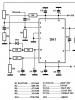
When assembling an amplifier on microcircuits, the TDA7294 is not a bad choice. Well, however, we will not dwell on the technical characteristics, you can see them in the PDF file TDA7294_datasheet, located in the folder for downloading material for assembling this ULF. As you already understood from the title of the article, this is a complete amplifier circuit that contains a power supply, signal pre-amplification stages with a three-band tone control, implemented on two common 4558 operational amplifiers, two channels of final stages, as well as a protection unit. The circuit diagram is shown below:
With a supply voltage of ±35 Volts into an 8 Ohm load, you get 70 Watts of power.
The PCB sources are as follows:


PCB LAY6 format:
Arrangement of elements on the amplifier board:
Photo view of LAY board format:
The board has a J5 connector for connecting a temperature sensor (Bimetal Thermostat), designated B60-70. In normal mode, its contacts are open; when heated to 60°C, the contacts close and the relay turns off the load. In principle, you can also use thermal sensors with normally closed contacts designed to operate at 60...70°C, but you need to connect it to the gap between the emitter of transistor Q6 and the common wire, while connector J5 is not used. If you are not going to use this function, leave connector J5 empty.
Operational amplifiers are installed in sockets. Relay with an operating voltage of 12 Volts with two groups of switching contacts, the contacts must withstand 5 Amps.
Printed circuit board for LAY6 fuses:
Photo view of the LAY format of the fuse board:
The power connector for the protection unit is located on the board just above connector J5. Just make a jumper with two wires between this connector and the main power connector as shown in the picture below:

External connections:
Additional Information:
4Ohm – 2x18V 50Hz
8Ohm – 2x24V 50Hz
With a power supply of 2x18V 50Hz:
Resistors R1, R2 – 1 kOhm 2W
Resistor RES – 150 Ohm 2W
With a power supply of 2x24V 50Hz:
Resistors R1, R2 – 1.5 kOhm 2W
Resistor RES – 300 Ohm 2W
The JRC4558 operational amplifier can be replaced with NE5532 or TL072.
Please note that on the conductor side of the printed circuit board, an LL4148 diode in SMD version is installed between the contacts of the relay coil; you can solder a regular 1N4148.
There is a GND point on the board near the volume control; it is intended for grounding the housings of all controllers. This piece of bare copper wire is clearly visible in the main picture of the news.
List of elements for repeating the amplifier circuit on the TDA7293 (TDA7294):
Electrolytic capacitors:
10000mF/50V – 2 pcs.
100mF/50-63V – 9 pcs.
22mF – 5 pcs.
10mF – 6 pcs.
47mF – 2 pcs.
2.2mF – 2 pcs.
Film capacitors:
1 mF – 8 pcs.
100n – 8 pcs.
6n8 – 2 pcs.
4n7 – 2 pcs.
22n – 2 pcs.
47n – 2 pcs.
100pF – 2 pcs.
47pF – 4 pcs.
Resistors 0.25W:
220R – 1 pc.
680R – 2 pcs.
1K – 6 pcs.
1K5 – 2 pcs.
3K9 – 4 pcs.
10K – 10 pcs.
20K – 2 pcs.
22K – 8 pcs.
30K – 2 pcs.
47K – 4 pcs.
220K – 3 pcs.
Resistors 0.5W:
2W resistors:
RES - 300R – 2 pcs.
100R – 2 pcs.
Diodes:
Zener diodes 12V 1W – 2 pcs.
1n4148 – 1 pc.
LL4148 – 1 pc.
1n4007 – 3 pcs.
Bridge 8...10A – 1 pc.
Variable resistors:
A50K – 1 pc.
B50K – 3 pcs.
Chips:
NE5532 – 2 pcs.
TDA7293 (TDA7294) – 2 pcs.
Connectors:
3x – 1 pc.
2x – 2 pcs.
Relay – 1 pc.
Transistors:
BC547 – 5 pcs.
LM7812 – 1 pc.
You can download the circuit diagram of the amplifier for TDA7294, TDA7294_datasheet, printed circuit boards in LAY6 format in one file from our website. Archive size – 4 Mb.
Updated: 04/27/2016
An excellent amplifier for home can be assembled using the TDA7294 chip. If you are not strong in electronics, then such an amplifier is an ideal option; it does not require fine tuning and debugging like a transistor amplifier and is easy to build, unlike a tube amplifier.
The TDA7294 microcircuit has been in production for 20 years and has still not lost its relevance and is still in demand among radio amateurs. For a novice radio amateur, this article will be a good help in getting to know integrated audio amplifiers.
In this article I will try to describe in detail the design of the amplifier on the TDA7294. I will focus on a stereo amplifier assembled according to the usual circuit (1 microcircuit per channel) and will briefly talk about the bridge circuit (2 microcircuits per channel).
TDA7294 chip and its features
TDA7294 is the brainchild of SGS-THOMSON Microelectronics, this chip is an AB class low-frequency amplifier, and is built on field-effect transistors.
The advantages of the TDA7294 include the following:
- output power, with distortion 0.3–0.8%:
- 70 W for 4 ohm load, conventional circuit;
- 120 W for 8 ohm load, bridge circuit;
- Mute function and Stand-By function;
- low noise level, low distortion, frequency range 20–20000 Hz, wide operating voltage range - ±10–40 V.
Specifications
| Technical characteristics of the TDA7294 chip | |||||
|---|---|---|---|---|---|
| Parameter | Conditions | Minimum | Typical | Maximum | Units |
| Supply voltage | ±10 | ±40 | IN | ||
| Frequency range | Signal 3 db Output power 1W |
20-20000 | Hz | ||
| Long-term output power (RMS) | harmonic coefficient 0.5%: Up = ±35 V, Rн = 8 Ohm Up = ±31 V, Rн = 6 Ohm Up = ±27 V, Rн = 4 Ohm |
60 60 60 |
70 70 70 |
W | |
| Peak music output power (RMS), duration 1 sec. | harmonic factor 10%: Up = ±38 V, Rн = 8 Ohm Up = ±33 V, Rн = 6 Ohm Up = ±29 V, Rн = 4 Ohm |
100 100 100 |
W | ||
| Total harmonic distortion | Po = 5W; 1kHz Po = 0.1–50W; 20–20000Hz |
0,005 | 0,1 | % | |
| Up = ±27 V, Rн = 4 Ohm: Po = 5W; 1kHz Po = 0.1–50W; 20–20000Hz |
0,01 | 0,1 | % | ||
| Protection response temperature | 145 | °C | |||
| Quiescent current | 20 | 30 | 60 | mA | |
| Input impedance | 100 | kOhm | |||
| Voltage Gain | 24 | 30 | 40 | dB | |
| Peak output current | 10 | A | |||
| Operating temperature range | 0 | 70 | °C | ||
| Case thermal resistance | 1,5 | °C/W | |||
Pin assignment
| Pin assignment of the TDA7294 chip | |||
|---|---|---|---|
| IC output | Designation | Purpose | Connection |
| 1 | Stby-GND | "Signal Ground" | "General" |
| 2 | In- | Inverting input | Feedback |
| 3 | In+ | Non-inverting input | Audio input via coupling capacitor |
| 4 | In+Mute | "Signal Ground" | "General" |
| 5 | N.C. | Not used | – |
| 6 | Bootstrap | "Voltage boost" | Capacitor |
| 7 | +Vs | Input stage power supply (+) | |
| 8 | -Vs | Input stage power supply (-) | |
| 9 | Stby | Standby mode | Control block |
| 10 | Mute | Mute mode | |
| 11 | N.C. | Not used | – |
| 12 | N.C. | Not used | – |
| 13 | +PwVs | Output stage power supply (+) | Positive terminal (+) of the power supply |
| 14 | Out | Exit | Audio output |
| 15 | -PwVs | Output stage power supply (-) | Negative terminal (-) of the power supply |
Note. The microcircuit body is connected to the power supply negative (pins 8 and 15). Do not forget about insulating the radiator from the amplifier body or insulating the microcircuit from the radiator by installing it through a thermal pad.
I would also like to note that in my circuit (as well as in the datasheet) there is no separation of input and output lands. Therefore, in the description and in the diagram, the definitions of “general”, “ground”, “housing”, GND should be perceived as concepts of the same sense.
The difference is in the cases
The TDA7294 chip is available in two types - V (vertical) and HS (horizontal). The TDA7294V, having a classic vertical body design, was the first to roll off the production line and is still the most common and affordable.

Complex of protections
The TDA7294 chip has a number of protections:
- protection against power surges;
- protection of the output stage from short circuit or overload;
- thermal protection. When the microcircuit heats up to 145 °C, the mute mode is activated, and at 150 °C the standby mode is activated;
- protection of microcircuit pins from electrostatic discharges.
Power amplifier on TDA7294
A minimum of parts in the harness, a simple printed circuit board, patience and known good parts will allow you to easily assemble an inexpensive TDA7294 UMZCH with clear sound and good power for home use.
You can connect this amplifier directly to the line output of your computer sound card, because The nominal input voltage of the amplifier is 700 mV. And the nominal voltage level of the linear output of the sound card is regulated within 0.7–2 V.
Amplifier block diagram

The diagram shows a version of a stereo amplifier. The structure of the amplifier using a bridge circuit is similar - there are also two boards with TDA7294.
- A0. power unit
- A1. Control unit for Mute and Stand-By modes
- A2. UMZCH (left channel)
- A3. UMZCH (right channel)
Pay attention to the connection of the blocks. Improper wiring inside the amplifier may cause additional interference. To minimize noise as much as possible, follow several rules:
- Power must be supplied to each amplifier board using a separate harness.
- The power wires must be twisted into a braid (harness). This will compensate for the magnetic fields created by the current flowing through the conductors. We take three wires (“+”, “-”, “Common”) and weave them into a pigtail with a slight tension.
- Avoid ground loops. This is a situation where a common conductor, connecting blocks, forms a closed circuit (loop). The connection of the common wire must go in series from the input connectors to the volume control, from it to the UMZCH board and then to the output connectors. It is advisable to use connectors isolated from the housing. And for input circuits there are also shielded and insulated wires.
List of parts for PSU TDA7294:

When purchasing a transformer, please note that the effective voltage value is written on it - U D, and by measuring it with a voltmeter you will also see the effective value. At the output after the rectifier bridge, the capacitors are charged to the amplitude voltage - U A. The amplitude and effective voltages are related by the following relationship:
U A = 1.41 × U D
According to the characteristics of the TDA7294, for a load with a resistance of 4 Ohms, the optimal supply voltage is ±27 volts (U A). The output power at this voltage will be 70 W. This is the optimal power for the TDA7294 - the distortion level will be 0.3–0.8%. There is no point in increasing the power supply to increase power because... the level of distortion increases like an avalanche (see graph).

We calculate the required voltage of each secondary winding of the transformer:
U D = 27 ÷ 1.41 ≈ 19 V
I have a transformer with two secondary windings, with a voltage of 20 volts on each winding. Therefore, in the diagram I designated the power terminals as ± 28 V.
To obtain 70 W per channel, taking into account the efficiency of the microcircuit of 66%, we calculate the power of the transformer:
P = 70 ÷ 0.66 ≈ 106 VA
Accordingly, for two TDA7294 this is 212 VA. The nearest standard transformer, with a margin, will be 250 VA.
It is appropriate to state here that the power of the transformer is calculated for a pure sinusoidal signal; corrections are possible for a real musical sound. So, Igor Rogov claims that for a 50 W amplifier, a 60 VA transformer will be sufficient.
The high-voltage part of the power supply (before the transformer) is assembled on a 35x20 mm printed circuit board; it can also be mounted:

The low-voltage part (A0 according to the structural diagram) is assembled on a 115x45 mm printed circuit board:

All amplifier boards are available in one.
This power supply for the TDA7294 is designed for two chips. For a larger number of microcircuits, you will have to replace the diode bridge and increase the capacitor capacity, which will entail a change in the dimensions of the board.
Control unit for Mute and Stand-By modes
The TDA7294 chip has a Stand-By mode and a Mute mode. These functions are controlled through pins 9 and 10, respectively. The modes will be enabled as long as there is no voltage on these pins or it is less than +1.5 V. To “wake up” the microcircuit, it is enough to apply a voltage greater than +3.5 V to pins 9 and 10.
To simultaneously control all UMZCH boards (especially important for bridge circuits) and save radio components, there is a reason to assemble a separate control unit (A1 according to the block diagram):

Parts list for control box:
- Diode (VD1). 1N4001 or similar.
- Capacitors (C1, C2). Polar electrolytic, domestic K50-35 or imported, 47 uF 25 V.
- Resistors (R1–R4). Ordinary low-power ones.
The printed circuit board of the block has dimensions of 35×32 mm:

The control unit's task is to ensure silent switching on and off of the amplifier using the Stand-By and Mute modes.
The operating principle is as follows. When the amplifier is turned on, along with the capacitors of the power supply, capacitor C2 of the control unit is also charged. Once it is charged, Stand-By mode will turn off. It takes a little longer for capacitor C1 to charge, so Mute mode will turn off second.
When the amplifier is disconnected from the network, capacitor C1 discharges first through diode VD1 and turns on the Mute mode. Then capacitor C2 discharges and sets the Stand-By mode. The microcircuit becomes silent when the power supply capacitors have a charge of about 12 volts, so no clicks or other sounds are heard.
Amplifier based on TDA7294 according to the usual circuit
The microcircuit's connection circuit is non-inverting, the concept corresponds to the original one from the datasheet, only the component values have been changed to improve the sound characteristics.
Parts List:
- Capacitors:
- C1. Film, 0.33–1 µF.
- C2, C3. Electrolytic, 100-470 µF 50 V.
- C4, C5. Film, 0.68 µF 63 V.
- C6, C7. Electrolytic, 1000 µF 50 V.
- Resistors:
- R1. Variable dual with linear characteristic.
- R2–R4. Ordinary low-power ones.
Resistor R1 is double because stereo amplifier. Resistance of no more than 50 kOhm with a linear rather than logarithmic characteristic for smooth volume control.
Circuit R2C1 is a high-pass filter (HPF) that suppresses frequencies below 7 Hz without passing them to the amplifier input. Resistors R2 and R4 must be equal to ensure stable operation of the amplifier.
Resistors R3 and R4 organize a negative feedback circuit (NFC) and set the gain:
Ku = R4 ÷ R3 = 22 ÷ 0.68 ≈ 32 dB
According to the datasheet, the gain should be in the range of 24–40 dB. If it is less, the microcircuit will self-excite; if it is more, distortion will increase.
Capacitor C2 is involved in the OOS circuit; it is better to take one with a larger capacitance to reduce its effect on low frequencies. Capacitor C3 provides an increase in the supply voltage of the output stages of the microcircuit - “voltage boost”. Capacitors C4, C5 eliminate noise introduced by wires, and C6, C7 complement the power supply filter capacitance. All amplifier capacitors, except C1, must have a voltage reserve, so we take 50 V.
The amplifier's printed circuit board is single-sided, quite compact - 55x70 mm. When developing it, the goal was to separate the “ground” with a star, ensure versatility and at the same time maintain minimal dimensions. I think this is one of the smallest boards for TDA7294. This board is designed for installation of one microcircuit. For the stereo option, accordingly, you will need two boards. They can be installed side by side or one above the other like mine. I’ll tell you more about versatility a little later.

The radiator, as you can see, is indicated on one board, and the second, similar one, is attached to it from above. Photos will be a little further.
Amplifier based on TDA7294 using a bridge circuit
A bridge circuit is a pairing of two conventional amplifiers with some adjustments. This circuit solution is designed for connecting acoustics with a resistance of not 4, but 8 ohms! Acoustics are connected between the amplifier outputs.
There are only two differences from the usual scheme:
- the input capacitor C1 of the second amplifier is connected to ground;
- added feedback resistor (R5).
The printed circuit board is also a combination of amplifiers according to the usual circuit. Board size – 110×70 mm.

Universal board for TDA7294
As you have already noticed, the above boards are essentially the same. The following version of the printed circuit board fully confirms the versatility. On this board you can assemble a 2x70 W stereo amplifier (regular circuit) or a 1x120 W mono amplifier (bridged). Board size – 110×70 mm.


Note. To use this board in a bridge version, you need to install resistor R5 and install jumper S1 in a horizontal position. In the figure, these elements are shown as dotted lines.
For a conventional circuit, resistor R5 is not needed, and the jumper must be installed in a vertical position.
Assembly and adjustment
Assembling the amplifier will not pose any particular difficulties. The amplifier does not require any adjustment as such and will work immediately, provided that everything is assembled correctly and the microcircuit is not defective.
Before first use:
- Make sure the radio components are installed correctly.
- Check that the power wires are connected correctly, do not forget that on my amplifier board the ground is not centered between plus and minus, but on the edge.
- Make sure that the microcircuits are isolated from the radiator; if not, then check that the radiator is not in contact with ground.
- Apply power to each amplifier in turn, so there is a chance you won’t burn out all the TDA7294 at once.
First start:
- We do not connect the load (acoustics).
- We connect the amplifier inputs to ground (connect X1 to X2 on the amplifier board).
- We serve food. If everything is fine with the fuses in the power supply and nothing smokes, then the launch was a success.
- Using a multimeter, we check the absence of direct and alternating voltage at the output of the amplifier. A slight constant voltage is allowed, no more than ±0.05 volts.
- Turn off the power and check the chip body for heating. Be careful, the capacitors in the power supply take a long time to discharge.
- We send a sound signal through a variable resistor (R1 according to the diagram). Turn on the amplifier. The sound should appear with a slight delay, and disappear immediately when turned off; this characterizes the operation of the control unit (A1).
Conclusion
I hope this article will help you build a high-quality amplifier using the TDA7294. Finally, I present a few photos of the assembly process, do not pay attention to the quality of the board, the old PCB is unevenly etched. Based on the assembly results, some edits were made, so the boards in the .lay file are slightly different from the boards in the photographs.


The amplifier was made for a good friend, he came up with and implemented such an original housing. Photos of the assembled stereo amplifier on the TDA7294:


On a note: All printed circuit boards are collected in one file. To switch between “signatures”, click on the tabs as shown in the figure.

list of files
We present to your attention a 100W class H stereo ULF, which is easy to assemble even for novice radio amateurs. TDA7294 integrated circuit in a monolithic Multiwatt15 package. It has a wide supply voltage range of +/-40V and can provide high output power into 4 and 8 ohm loads.
There is built-in protection against short circuit in the load and protection against overheating (upon reaching 145 degrees).
There is also a Mute function, which is used to eliminate clicks when turned on, and a standby mode. Reproducible frequency range 20-20000Hz. Total harmonic distortion no more than 0.1%.
Please note that the IC body is connected to -Vcc, so it should not be installed in a metal case without insulation. Otherwise, a short circuit to ground will occur. Before screwing the chip to the heatsink, do not forget to apply thermal paste.
Below is a schematic diagram of a power amplifier based on the TDA7294 chip.

The photo shows only one of the amplifier channels.

The pictures show the printed circuit board and the arrangement of parts on it.


The photographs show the sequence of board assembly
Notes:
The TDA7294 IC is not compatible with 1% tolerance resistors.
About 1000uF filter capacitors: If you are using speakers larger than 10 inches in diameter, you should increase the capacitors to 2200uF.
Selecting a 47uF capacitor: I recommend using 47uF 50V manufactured by Elna SilmicII and 47uF 50V manufactured by Nichicon MUSE KZ.