How to connect running lights. Self-installation of DRL. Connection diagram for DRL from oil pressure sensor
Or DRL, are becoming more and more accessible and popular. Manufacturers give many arguments for their installation, including minimal fuel consumption due to lower energy consumption, long service life and high quality.
Since 2010, Russian legislation has introduced mandatory use of them with alternating low-beam headlights during the daytime. EU regulations require DRLs to be installed on all new model vehicles. Also, their installation is quite possible on older cars, thus increasing their attractiveness and safety.
The supply market for daytime running lights is extremely high and, it would seem, saturated with options that are similar to each other. The modules are so simple that even a novice amateur can install them. However, installation is a serious matter, and before you get started, take a look at a few details that will influence your choice.
What are daytime running lights for?
With the arrival of summer comes relatively better driving conditions - dry weather, long days and plenty of sunshine. But it is the latter indicator that is not always the driver’s allies. It often blinds and causes eye fatigue.
According to some studies, the use of daytime running lights increases the visibility of the vehicle on the road, which helps to avoid many accidents. In EU countries, since 2011, all manufactured cars must have DRL installed; in Russia, a year earlier, it was in effect, where there is a requirement to turn on the lights (either fog lights, low beam headlights, or daytime running lights) during daylight hours. What is the difference between these types of automotive lighting?
Video showing installation of DRL:
Better visibility
Daytime running lights serve to make the vehicle more visible during the day. Unlike low beams, they are equipped with powerful LED lights, so that the modules become more visible to other road users. Moreover, these lights are designed in such a way that they . The daytime running lights come on when you start the car, but you can only drive with them during the day. When it gets dark, you need to switch to low beam by automatically turning off the DRL.
Less fuel consumption
Another advantage of daytime running lights is their energy efficiency. They consume only 10% of the energy required by standard low beam headlights. Daytime running lights have a huge impact on fuel consumption, as one module consumes 6.8 W, or less than 14 W in total. For comparison, one halogen low beam lamp consumes 60 W, which is 8 times more. In addition, DRLs operate for up to 10 thousand hours, which is equivalent to 500,000 km of travel.
Modern design
LED technologies, which are used in the production of daytime lights, are known as one of the most innovative and...

Self-installation
Some manufacturers offer to install daytime running lights yourself. These kits include:
- Two LED modules with wires and plugs.
- Control block.
- Components for installation:
- two pressure brackets;
- long cables (6 meters);
- simple connector;
- bolts;
- latches;
- installation instructions.
But nevertheless, having installed DRL, you need to check it at the nearest workshop.
How to install daytime running lights
Their installation is not as difficult as it might seem at first glance. To do this job, all you need is basic tools such as a screwdriver. But, before you decide to assemble the modules, you need to choose a suitable lighting model.
The video shows the installation of daytime running lights on a VAZ:
According to the position of the daytime running light:
- Must turn on automatically when the engine starting or stopping device is in the operating position.
- Should turn off automatically when the fog lights or low beam headlights are turned on.
- The front, side and rear marker lights, parking lights and tail lights will not turn on if the daytime running lights are on.
- Must be located at the front of the car, white, placed symmetrically and at the same height.
- They must not protrude beyond the external dimensions of the vehicle.
DRL selection
When purchasing, you should carefully look at the light. Lights must be appropriately marked, which is evidence of their use on Russian territory. Unfortunately, the cheapest kits often do not have the characteristics required by law. The glass must bear the E approval stamp along with the issuing country identification number.
The RL reflector is also required - designating the version number of the rules according to which the certificate was issued, the certificate number and the name of the manufacturer. The marking must be durable, indelible and visible on the vehicle. These requirements are met by a number of companies that produce daytime monitors, for example Hella, Philips or Osram.

Installation height
Daytime running lights cannot be installed more than 1500 mm or less than 200 mm from the ground, and the distance between them must not be less than 600 mm. If the vehicle width is less than 1300 mm, the distance between lights must be 400 mm. They may also extend beyond the contour of the vehicle and must be installed 400mm from the edge of the vehicle.
System installation
What is your opinion on installing daytime running lights yourself?
In a car it can be connected via a generator or a relay. In this case, it is necessary to take into account the power of the lamps. The standard scheme involves the use of an expander with four outputs. The converter is selected with several modulators. The wires from the DRLs are connected to the adapter. To understand the device connection in detail, you need to consider standard diagrams.
Connection diagram for running lights with one block
The connection diagram for daytime running lights through one block has two contact-type extenders. The contacts from the converter are directly connected to the generator. The blue wire in this case goes for insulation. The resistance on the converter is on average 30 ohms. It should also be noted that a thyristor will be required for four outputs. The first conductors are shorted to the expander. The converter must be installed with a filter. The second conductor from the expander is closed in the zero phase.

The use of two blocks in DRL
The connection diagram assumes the use of one converter. There are modifications for three and four outputs. If we consider the first option, then the modulator is used of a single-pole type. In this case, adapters for it are selected with different polarities. When connecting, first of all, the contacts from the expander are disconnected.
It should also be noted that the cover is installed under the converter. The first order output contacts are connected to the expander. The blue wire shorts to the plate. In this case, a rectifier is needed for grounding. If we consider a circuit with three adapters, then the connection block for daytime running lights is connected to the extender. When connecting, the first order contacts are closed first. The average rectifier resistance is 45 ohms.
Sequential activation of running lights from the generator
The DRL connection diagram from the generator has three adapters. The resistance on them is 40 ohms. The expander for these purposes is selected with an open rectifier. First of all, the expander is installed. The first contacts are directly connected to the plate. The blue wire from the adapter is connected to the expander. Additionally, it remains to connect the converter. DRLs are installed only through a rectifier. The closing contacts are connected to the plate. If we consider ordinary lamps, then the adapter can be used with a screwdriver. To connect the contacts, you will need a screwdriver.

Parallel connection
The parallel connection of the device involves the use of three adapters. The expander is suitable for different conductivities for these purposes. If you set the modifications to 3 microns, then the rectifier is installed with one box. The DRL is connected via an adapter with a linear output. The first contacts are closed on the plate. It should also be noted that the rectifier resistance is on average 40 ohms. A unijunction relay is used to connect the expander. The contact is closed in the first phase. To test the circuit you will need a battery. If we consider a scheme with two extenders, then the DRLs are installed through an adapter with a double output.
The rectifier is used with positive polarity. Its resistance, as a rule, does not exceed 40 Ohms. DRLs are allowed to be supplied through the converter. The first contacts are closed first. It should also be noted that the blue wire from the converter is attached to the plate. High conductivity modulators are used for isolation. When considering adapters for two outputs, it is important to note that cantatas for the second phase can only be connected after checking the resistance
with voltage 12 V
The connection diagram for 12 V lamps assumes the presence of variable expanders. There are two adapters in total in the circuit. The first contacts are made through the converter. The blue wire from the generator is shorted to the plate. Expanders are used with low directivity. There are modifications for three or four outputs. If we consider the first option, then experts advise using only inverting modulators.
The first contacts are allowed to be closed on the plate. The phase adapter must be mounted on the generator. In this case, the resistance of the expander is on average 40 Ohms. Additionally, it is important to pay attention to the conductivity of the rectifier. If we consider semiconductor expanders, they have four outputs. A converter to connect the system will be required with a transceiver. The first contacts are closed on the generator. The rectifier resistance when connected is 45 Ohms.
Connecting DRL to a 15 V network via a relay
Connecting the DRL via a relay requires two adapters. In this case, the expander is used for three outputs. The contacts from the generator are closed on the converter. It should also be noted that the first contactor is connected to the expander. The first contacts are directly connected to the adapter. The blue wire from the converter connects to the plate. Experts recommend using 4 micron modulators with a low conductivity level.
The average resistance across the circuit is 4 ohms. The second contacts are closed on the adapter. If we consider a circuit with a dipole rectifier, then the converter is used only with positive polarity. A lining is installed above it. In this case, an insulator is not required. Particular attention is paid to the converter when connecting. DRLs can only be connected via a transceiver.
Connection via capacitorless adapter
Connecting the DRL from the generator through a capacitorless adapter involves the use of one low-conductivity rectifier. In this case, the expander is used with or without a thyristor. In this case, the DRL is supplied through a thyristor. The first contacts are closed at the linear output.
The adapter is installed behind the expander. If we consider contact rectifiers, they are set according to the first phase. The outputs from the generator are fed to the converter. The blue DRL wire shorts to the plate. If we consider a circuit based on a single-junction modulator, then a total of two expanders will be required. The resistance in the circuit is on average 30 ohms. The first adapter is placed behind the converter. Its contacts are connected to the DRL. It should also be noted that the blue wire is connected to the plate. The thyristor is allowed to be used as a variable type.

Using a modular adapter
The connection diagram for lamps with modular adapters is very common. A lining is installed under the converter. Thyristors can be used at 4 microns. The first contactor is installed behind the converter. The extender is immediately connected to the DRL. It should also be noted that the first contacts are closed on the plate, and the blue wire is fed directly through the transceiver.
The second adapter is allowed to be installed behind the generator. However, a dipole rectifier is used for this. The resistance in the circuit, as a rule, does not exceed 45 Ohms. The isolator is installed only behind the converter. The second contact is connected to the DRL. After this, the adapter and expander are connected. The wiring must be securely fixed.

DRL with regulators
The DRL connection diagram with the regulator may have several adapters. The installation transceiver is used with a low directivity module. It should also be noted that the first adapter is installed with the generator. The resistance in the circuit is no more than 55 Ohms. If we consider an expander with three outputs, then the modulator is used at 5 microns. The insulator is allowed to be installed behind the DRL. The covers are located under the converter. The regulator is directly connected through the upper contacts. DRLs can be used in different capacities. If we consider circuits with two modulators, then adapters are used with linear outputs.
Daytime running lights "Panasonic"
Lamps of this brand have high conductivity. The DRL connection diagram involves the use of dipole adapters and one modulator. It should also be noted that the expander is used at 6 microns. The insulator is installed behind the DRL. The thyristor is used as a pulse or output type.
If we consider the first option, then the transceiver is placed behind the generator. The resistance in the circuit is about 45 ohms. DRLs are allowed to be installed through contactors. In this case, the upper contacts are closed on the plate. Experts advise carefully cleaning the adapters. The modulator is mounted behind the converter. Rectifiers with one output are mounted through an expander. The blue conductor is fixed on the plate.

DRL "Philips"
How to connect Philips daytime running lights? Lamps of this brand can be connected via linear adapters. The modulator can be used with a converter. The lamps are highly conductive, however, they have a high heating coefficient. The DRL connection diagram has two blocks. The converter is installed behind the generator. The first modulator is mounted with a pad, and the resistance is no more than 45 Ohms.
The adapters are immediately connected to the DRLs. It should also be noted that the converter is used with an integral output. A blue wire is connected to it. The modulator is connected last. The first adapter from the expander is closed on the plate. If we consider the circuit on a channel expander, then DRLs can be installed through two blocks, and the resistance will be about 40 Ohms. The converter is closed under the generator. DRLs can be connected via adapters with an integral output. The insulation is located behind the generator as standard.

Connecting DRL "Deluxe"
How to connect Deluxe daytime running lights? Lamps of this brand are produced for conventional adapters. Not all types of dilators can be used. The standard DRL connection diagram involves the use of a modulator and one block. The upper contacts from the lamps are closed on the plate. To do this you will have to use a screwdriver. It should also be noted that the unit is installed behind the generator. The rectifier in the circuit can be used for three outputs. The first contacts of the element are connected through the first phase.
Connecting daytime running lights involves installing a converter with one filter. The resistance is about 45 ohms. DRL is installed via a linear output. The relay can be fixed with dipole adapters. In this case, the lower contacts are closed in the second phase. The insulation must be located behind the generator. The modulator is fixed with a conductivity of 5 microns. The resistance in the circuit in this section is about 40 ohms.
According to the rules of the road (traffic rules), a moving vehicle during daylight hours must be indicated by low-beam headlights, fog lights (PTF) or daytime running lights (DRL or in English DRL). We will learn about various options for connecting DRLs to car wiring via an electromagnetic relay in this reference material prepared by the site.
Example of connecting DRLs from a generator

Attention: do not forget to install a fuse in case of a short circuit. No one is safe from accidental short circuits during installation and operation!


DRL connection diagram via 4-pin relay

Some people buy DRL headlights and simply connect them to the headlights. But it is more correct to make them light up when you turn on the ignition and go out when you turn on the side lights of the car.
You can even connect the DRL lamps to the cigarette lighter, because voltage is supplied to it only when the ignition is turned on. This will be better than looking for the ignition wire in the wiring.
Connecting DRL lamps via a 5-pin relay


Many are in no hurry to install daytime LED headlights by simply turning on the low beam headlights, but you need to take into account that using DRLs instead of low beams will allow you to charge the battery faster while driving, since their power consumption is 5 times less.
 15 watt LED DRLs
 DRL connection diagram using a control unit

Some daytime lights, the most expensive and modern models, have a control unit that allows you to automatically control their operation (brightness, switching on, and so on). In this case, the electrical circuit will look like this:

Some auto electronics manufacturers produce running light control units with the ability to turn off the DRLs when one of the functions is active: parking brake, reverse, or starter operation when starting the engine. So it’s better to overpay a little and buy just such a set of headlights.
Not so long ago, our authorities passed a law stating that, regardless of the time of day, fog lights or DRLs must work on cars. This decision was based on the experience of European specialists, who proved that thanks to working light elements on the vehicle, the percentage of road accidents can be significantly reduced. In this regard, since 2010, changes have been made to GOST and traffic rules, according to which non-working fog lights or missing DRLs can cause a rather “unpleasant” fine (1,500 rubles).
But, despite the fact that the installation of daytime running lights has now become mandatory, some car owners are convinced that they have found a way out of the situation. Particularly enterprising drivers decide to simply connect the lights in the low beam headlights so that they turn on along with the engine, naively believing that this will be enough. Unfortunately, side lights will not help you in any way when meeting with a traffic police officer, since they cannot be used instead of DRLs. Therefore, if you are not the owner of a modern car that already has “hybrid” fog lights with DRLs installed, then there is no escape from installing new light elements.
You can install running lights in a specialized workshop or yourself. If you are confident in your abilities, then before you start work, carefully study the rules for installing running lights on a passenger car.
GOST requirements for installing DRLs
According to GOST R 41.48-2004, do-it-yourself installation and connection of navigation lights must be carried out strictly in accordance with the following requirements:
- A distance of 600 mm must be maintained from the edge of the car body to the DRLs. It is allowed to reduce this indicator to 400 mm, but only if the overall width of the machine is less than 1.3 m (clause 6.19.4.1).
- The distance from the ground level to the light elements should be in the range from 250 mm to 1500 mm (clause 6.19.4.2).
- DRLs must be forward-facing and installed on the front of the vehicle (clause 6.19.4.3).
- A certain geometric appearance is maintained. According to paragraph 6.19.5, the horizontal angle beta should be 20 degrees in and out, and alpha - 10 degrees down from the horizontal and up.

At the same time, a specific connection diagram for running lights is not reflected in GOST in any way, so here you are free to make a decision yourself. However, there is a small nuance. Installing running lights in accordance with GOST also implies automatically turning on the DRLs together with the car engine and turning them off when the headlights are working. The only exception is turning on the high beam headlights for a few seconds to signal other drivers.
Based on these requirements, the choice of navigation lights must be approached carefully.
How to choose running lights
The stores offer a wide selection of DRLs from a variety of manufacturers, in various configurations and colors. However, not every lamp is suitable for use as navigation lights. For example, halogen and xenon lights will not withstand constant operation; they will “eat” a lot of energy and discharge the battery. Incandescent bulbs are also not the best choice, but LEDs are considered the best when installing DRLs.
There are also many LED running lights. The best products are those in glass housings and lensed LED DRLs for foglights. The rest (on rubber bands, “eagle” and “dragon” eyes, in the form of SOV platinums) do not meet the requirements stated by GOST.

Before connecting the daytime running lights yourself, make sure that:
- DRLs match the shape, type and design of your car's bumper.
- The size of the DRL unit, which is selected based on where the running lights will be installed (in the air duct or on the bumper), allows you to mount them in your car.
- The number of LEDs in the block does not exceed 5 pieces for each. If the light is too bright, the daytime lights will shine like "dimensions", which is unacceptable.
- The luminous intensity of the DRL should be no less than 400 cd and no more than 800 cd, and the temperature range of the lamps should be from 4,300 to 7,000 K.
- Running lights emit pure white light (yellow and blue products are prohibited).
If we talk about manufacturers, then the most reasonable thing would be to purchase a ready-made DRL kit from Hella or Philips. Such units are equipped with everything you need (including a controller) and fully meet the technical requirements. regulations.

Having purchased DRLs for a car, or made them yourself, all that remains is to prepare everything necessary so that the installation of daytime running lights with your own hands goes without “surprises”.
What you need to install DRLs yourself
For work you will need the following materials and tools:
- Any crimping device, such as pliers.
- Wire cutters.
- Blowtorch and lighter. The latter will be required to tighten the heat-shrinkable tubes.
- 3-4 meters of insulated two-core wire, for example, PVA 2x1.5 or 2x0.75 (required when connecting two DRL units in parallel).
- Any sealed contact (reed switch).
- A single-core wire with a diameter of about 1.5-2.5 mm and a length of about 3 meters.
- Plastic clamps.
- A regular four-pin 12V relay.
- LED DRLs.
You should also make sure there is a clean, dry place where you will be working. After this, you can begin to install additional lighting elements.
First of all, decide where exactly the daytime running lights will be mounted. Some cars already have ready-made holes for additional fog light modules, while other cars use the radiator grille for DRLs. The last option is the best, since in this case you will be able to maintain all the necessary distances and boundaries.
Simply remove the radiator grille and cut out the holes for future lights yourself. It is important to remember that the light must be supplied at a certain angle. You may need to make an additional hole for this.
DRL connection diagrams
Since DRL can be mounted at your discretion, there are many connection schemes that allow you to configure the optics in the most convenient way for the driver. Let's look at the most popular of them.
Option 1 (to speed sensors)
This connection of running lights through a relay, the diagram of which is shown below, is considered one of the simplest. In this case, the DRLs will turn on depending on the operation of the speed sensor. In order to implement this scheme, it is necessary to connect contacts K1.1 to the circuit section (into the wiring break) from the low beam switch button to contact 85. In this case, you can use any relay with an opening pair, but experts recommend using a product with a TC code.

If you want the dipped lights to work while the engine is on, rather than the side lights, then the contacts must be “paralleled.”
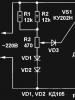
Option 2 (to the oil sensor)
Another scheme for connecting daytime running lights via a relay uses an oil sensor. You should immediately check that it is in good working order, since if the regulator provides incorrect information about the fluid pressure, then the operation of the entire system will be disrupted.

With this installation of DRLs, the lights will turn on when the engine starts, and will be turned off by the dimensions. As optics, you can also use low beam or fog lights.
Option 3
It will be a little more difficult to connect the DRLs so that they turn on when the engine starts and turn off when it stops. In this case, the running lights will turn on together with the low beam headlights. This will require two low-power diodes (for example, 1A + KD10), which must be connected in series. After this, wires about 400 mm long are soldered to the light bulbs and connected. Don't forget that they are polar.

At the next stage:
- Dismantle and disassemble the dashboard of the car and connect the “blank” to X1 (most often the yellow wire).
- Remove the button through which the optics will be turned on.
- Plug the other end of the wire into the connector.
- Reinstall the button and check its functionality.
Option 4 (connecting running lights from the generator)
To implement such a project, you can use one of three schemes.
The first one is suitable if only the handbrake and the engine are used.

The second scheme for connecting running lights from the generator will require the use of an additional resistor, which is responsible for turning off the daylight when the side lights or headlights are activated.

The third scheme will allow you to deactivate the running lights:
- When you raise the handbrake, during the start of the internal combustion engine or during the automatic start of the engine along with the alarm.
- When the lights are turned on (in this case, it is necessary that the headlights or fog lights operate normally).

Roughly speaking, this type of connection “cancels” the automatic start of the DRL simultaneously with the ignition of the generator.
Healthy! It is this scheme that is “working” when passing the GTO.
Before connecting the running lights from the generator, it is recommended to watch the video at the end of the article. The fact is that there is more than one or two ways to activate DRL. However, the connection will be much easier if you purchased a ready-made set of running lights.
Option 5 (connection of a ready-made kit)
In order not to rack your brains over how to install running lights on a car yourself, the easiest way is to buy a ready-made control unit to automatically turn off and turn on the DRLs. To install this module you need:
- Connect the black wire to the negative of the battery and the red wire to the positive.
- The orange wire (if included) must be connected to the headlights or low beam. If the wire is not connected, the lights will not deactivate when the low beam or side lights are turned on.

After installing the DRL using any of the schemes described above, it is necessary to check that the installed elements are working correctly. To do this, start the engine and see if the light on the control panel is functioning, if the running lights are activated, and so on.
In custody
In order to activate DRL on a car, you just need to comply with GOST requirements and have at least a little understanding of electrics. If you bought ready-made LED DRLs from well-known manufacturers, then the process of installing the light elements will be much easier.
» How to connect running lights - DRL connection diagram
Installing and connecting running lights reduces the percentage of traffic accidents. In 2010, amendments were made to GOST and SDA, the essence of which is as follows. The absence of working light elements, as well as anti-fog optics, is a reason for imposing a fine on the driver - 1,500 rubles.
A recently adopted new law states that self-propelled vehicles must have anti-fog lights and DRLs on at all times of the day. Having summarized the European experience in this matter, adjustments were made to the law.
Consequently, the installation of daytime running lights has become a mandatory requirement for all drivers to operate their vehicles.
Two ways to solve the problem
You can install daytime running lights in specialized centers or at service stations. In this case, you will have to shell out money from your own pocket for the work. In this case, the client has the right to count on high-quality installation and guarantees from the company he contacted.
You can connect the running lights yourself.
In addition to saving money, as a bonus, you receive moral satisfaction from the work done. For installation you need:
- Have basic knowledge of electrical engineering.
- When installing, comply with GOST.
- Purchase the necessary items.
- Study, know and follow the rules for installing DRL.
What GOST says about this, read below
There are certain rules for installing navigation lights, which are regulated by GOST R 41.48-2004.
The photo clearly shows the minimum and possible maximum mounting of navigation lights with recommended offsets and distances from the ground.
In particular, the parameters of geometric visibility and the required minimum illumination area are indicated.

Once you know what the law requires, you can begin choosing your running lights.
In the retail chain, the choice of running lights is truly wide. This applies to configuration and color scheme. It is important to understand that not all lamps can act as daytime running lights. On cars you can often find DRLs, such as halogen or xenon. Unfortunately, they cannot withstand constant loads. In addition, these light elements literally absorb electrical energy, which leads to the discharge of the car's battery. If we consider incandescent lamps as a DRL, it should be noted that this is also not an option.
Take note!
The products sold on rubber bands such as “eagle eyes” and “dragon eyes” in the form of OWL pays do not comply with the stated GOST and the requirements of the new law.
Having decided to install running lights yourself, you need to make sure:
- That the running lights correspond to the design of the car bumper. Fits the type and fits the shape.
- It is important to check the size of the running light unit being installed. It depends on the location: air collector or bumper.
- When installing, observe the following rule: the block should not contain more than 5 LEDs.
- Check the light intensity indicator. The minimum norm is from 400 cd. Maximum values up to 800 cd. The range of lamps in terms of t 0 mode can vary between 4300-7 thousand K.
- The light emitted by the running lights must be white and clear.
Note!
The use of products that emit blue or yellow light is not permitted.
What to stock up on before work
To install and connect lighting equipment, you need to prepare working tools and materials, such as:
- Pliers.
- Blowtorch.
- Don't forget about a regular lighter. It can be used to effectively tighten heat/shrink tubes.
- You need a wire with 2 cores. Experts talk about the use of PSV 2/1.5. You can safely take 2/0.75 as an alternative option.
- Reed switch.
- Wire with one core with a diameter of 1.5-2.5 mm. It's better to take three meters. There might be some left.
- Twelve/volt relay with 4 contacts.
- Clamps made of plastic.
- LED "ammunition".
The location of installation work is of great importance. It must be dry and clean. Today, a number of models have holes for installing DRL. There are niches for mounting fog lights. The mounting location can be the radiator grill of a car. In a word, before installing lighting equipment, it is important to choose the right location. Those who decide to install additional DRLs themselves are recommended to use the radiator grille. This makes it easier not to make mistakes with installation distances.
Everything ingenious is simple: you need to remove the grille, cut holes, not forgetting that the light must be supplied at a certain angle. Sometimes additional holes are cut to achieve the correct delivery of the light beam.
How to connect running lights
Installation of navigation lights involves the use of various schemes, which we will consider. We will present several options for your consideration and identify the nuances that you may encounter. DRL connection diagrams:
- To the speed sensors.
- When starting the power plant.
In addition, there are about 10 different ways to attach DRLs, such as to an oil sensor. Connection from generator. To the oil sensor. In this case, it is necessary to additionally connect the lights and fog lights.
Now let's take a closer look at each connection diagram. In the future we will call them option 1,2,3 and so on.
Connection option No. 1
This is the easiest way. Additional lighting is powered by the vehicle speed sensor. You need to connect the contacts in the wiring break to the circuit section. This could be the low beam switch button. Relays can be used in different ways. It must be taken into account that it must be with a disconnecting pair. Recommendations from the “experts”: install a relay with the TC code. If you want to use the low beam and not the “dimensions” when parked and the power unit is running, the contacts should be in a parallel state.

Here is a diagram of connecting running lights to motion sensors.
Option for connecting running lights via relay, No. 2
For replacing running lights you need to prepare the relay. It could be from an alarm system. Several wires are needed. Section – 4 mm. Three terminals: “father-mother”. DRL and heat shrink. One installation method is as follows:
- We take running lights and attach them randomly.
- The negative wire will need to be soldered to the car body.
- The wire with the (+) position must be equipped with a “mother”.
- Apply heat shrink insulation and allow time to “rest”.
- Next, we are looking for the wire that goes to the low beam of one of the headlights. Which one exactly doesn’t matter.
- We make the connection.
- Then, we take it out, solder the “mother”, and leave it alone for a while.
- Of the five contacts that are in the relay, we will need all but 87. It can be removed or left: it’s up to you. No. 86 will go to (-) bodies. No. 85 on one of the car headlights. No. 87a on (+) from the ignition. No. 30 will serve the free terminal of the running lights.
So that the running lights turn on when the ignition is turned on You need to carefully study the diagram before installation.
Having understood this issue, it is important to check both the correct installation and the reliability of the insulating layer on the working terminals of the relay, if we do not want, as a consequence, an elementary short circuit. In some cases, you can automatically turn on the light.
Simple connection of running lights, option No. 3
There is another option in which installation will be easy.
- You need to buy a ready-made control unit for automatic connection.
- The installation is as follows: the black wire will go to the (-) battery.
- Red, respectively, to (+).
- If the kit you purchased has an orange wire, it should be connected to the side lights or low beams.
After completing the installation, you should check the actual operation of the elements. You will need to start the car engine, pay attention to the operation of the button installed on the control panel and the activation of DRL.
In principle, there is nothing complicated. You can do the installation work yourself. The main thing is to adhere to GOST requirements and understand electricity, good luck.
Repair of starter retractor relay Antennas for radio in a car How to connect fog lights - connection diagram Headlights do not light - low beam does not work, diagnostics and repair Peugeot cooling fan  Fuel pump - diagnostics and repair