Replacement of the light control unit. Replacing the light control unit What is mus on viburnum
The design of the light control unit on the Lada Kalina is quite reliable and most owners have never encountered problems with this module during the entire time they owned the car. But as always, there are exceptions to the rules, and this article was written just for those who were unlucky and this unit failed.
Replacing it is quite simple; you only need a regular flat-blade screwdriver. First you need to open the fuse cover, because this part is located on it. It is retracted quite simply, you just need to put in a little effort by pulling it towards you, as it is secured with thin metal clips.
Now you need to disconnect the plug with wires from the light control module itself. Squeeze the latches on both sides of the plug and pull it towards you, moving it from side to side. At this time, it is better to hold the lid, as it may fall off the latches.

And now you can remove the cover along with the module built into it, since nothing else holds it except flimsy latches, see the figure below:

When the cover has been removed, you can begin to remove the light block, but here you need to be extremely careful, since the design is very weak, it is held very tightly by two plastic latches on both sides, and to remove it you need to apply sufficient force by pressing a screwdriver on one from the latches on the inside and release one part of the part. The other one will come out very easily.

If you already have a new light control unit for Kalina, then replace it in the reverse order; it is inserted from the outside until it is secured with latches.

There is nothing complicated, the main thing is to be careful not to break the unreliable plastic latches that secure this module in the lid.
I leave work, get into the car, start it. The instrument panel lights come to life. I turn my face away from the radio, hook up the radar detector, and put the phone under my arm. You can go. I release the handbrake, the daytime running lights come on (according to the latest amendments to the traffic rules).
Dusk comes, it becomes dark - and the low beams turn on, and the running lights go out. I get home and turn off the engine. I take the junk out of the brightly lit trunk and put the car on the alarm. The lights go out until morning.
The proposed device controls the external lighting devices of the car: low beam headlights (BS), daytime running lights (DRL - daytime running lights), fog lights (PTF) and a clearance circuit, which is combined with instrument lighting and trunk lighting. The basis of the device is the ATMega8 microcontroller, the light sensor is a phototransistor under the windshield.
The device is implanted into the standard light control module (LCM) of the Lada Kalina, while all standard light control functions are retained - when manually turning on the side lights or headlights, the device will not interfere.
The main features of the device for which it was created:
1. Automatically turn on and off the low beam, depending on the darkness outside.
2. Automatic control of daytime running lights, in accordance with the state of the low beam (“DRL” lights up during the day, low beam at “night”).
3. In the dark - automatic switching on of the lights when disarming or when the ignition is turned off. The lights will go out when arming, or after 5 minutes of inactivity.
4. Control of standard fog lights and optionally remembering their state when the ignition is turned off.
And additional ones that were added during operation:
1. Turn off the BS / DRL 30 seconds after putting on the handbrake.
2. Recording thresholds for turning on and off the light by the user himself.
3. Display of the current light level and recorded thresholds in binary code.
4. Possibility of configuring the device directly from the control buttons.
5. Possibility of generating PWM with 30% fill to implement DRL mode on high beam headlights (this will be discussed in the appendix).
6. Turn on the light (BS or DRL) only after starting the engine, so as not to create additional load on the battery.
If the car is not equipped with separate running lights, you can use PTF or even low beam as them. True, in the latter case the meaning of the automatic light control function is completely lost :-)
Specifications:
Supply voltage: +9 .. +15 volts DC.
Current consumption: no more than 150 mA during operation, no more than 1 mA in sleep mode.
ADC capacity for illumination measurement: 10 bits.
User interface: 2 buttons, two LEDs (one of them is two-color).
Design: repeats the shape of the back cover of the light control module and is mounted on it.
The first version was created in October 2008, the latest version was created in November 2010.
Compatibility with cars: Kalina - without modifications, the rest - with minor modifications to the external circuits.
Device diagram
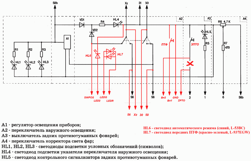
It is better to view the diagrams in separate files. Here is a diagram of the device itself:

The gray frame on the right is the elements of other car systems, and on the left is the inside of the light control module. The complete diagram of the modified MUS of the Kalina car of the Norma configuration is given below. The circuit for the luxury configuration differs only in cutting off the front PTF button from the standard circuit:
The device is based on the ATMega8 AVR microcontroller. Cheap, common and functional. It operates from a built-in RC oscillator at 1 MHz.
To measure illumination, phototransistor VT1 is used. Together with resistor R8, it forms a divider, the voltage from which is supplied to one of the ADC channels of the microcontroller (PC7). In the dark, the transistor is closed, and the voltage at the ADC input is close to 0; when illuminated, it opens and the voltage rises. Just like all the elements, the phototransistor is selected in the SMD version and is soldered to a small scarf glued under the windshield, but it can be replaced with any other one. In this case, you may have to change the resistance of resistor R8.
The microcontroller controls two relays installed on the board - K1 and K2, which are responsible for the low beam and side lights, respectively. The relay contacts are connected in parallel with the contacts of the MUS switch - see the diagram. The third relay is the PTF turn-on relay. It is standard, installed in the mounting block, controlled by the “plus”. To control the DRL, an open collector output is provided, which can operate in two modes. It will be written about in the appendix.
It would seem that the 21st century is just around the corner, why did I use a relay and not a MOSFET? And everything is very simple - if you use a MOSFET with a P-channel, it will need a radiator (you need to switch 10 amperes). A MOSFET with an N-channel will need a bootstrap circuit for control. And with a radiator or additional wiring, a MOSFET takes up more space on the board than a relay. And it costs more.
A relay marked “Beep block” is necessary on those cars that, when opening the door, remind the driver that the lights are not turned off. When the device turns on the lights in the dark with the ignition off, this relay (with normally closed contacts) breaks the “notification” circuit. On Kalina, for example, this circuit is a brown wire from the dimensions to the 13th contact of the immobilizer (it is he who is responsible for reminding about the forgotten dimensions in Kalina), a relay of the RES-55 type is conveniently placed directly on the immobilizer harness (in which you can also find the ground for second end of the winding).
If the headlights or headlights are turned on manually (using the handle on the light control module), the beep blocking is not activated.
The rear fog lights operate according to the standard algorithm, however, in order to assign additional functions to their button (long press action), the circuit from the button is broken inside the MCU and is simulated by a microcontroller (a pulse lasting 200 ms).
Instead of transistor switches, one assembly of 7 transistors - ULN2003A - is used to control the loads.
To recognize that the ignition is on, voltage is applied to leg PB7 of the microcontroller. It is limited by resistor R7 and zener diode VD2. Capacitor C3 filters, out of harm's way, all kinds of emissions.
The position of the light switch is detected by the PB6 foot. When the knob is in the "off" position, the switch contact we need is connected to the ignition circuit. The microcontroller program recognizes the presence of +12 volts in this circuit when the ignition is on, or low resistance to ground when it is off, and draws a conclusion about the position of the handle. Resistor R4 is needed to create resistance to ground when working on the table, otherwise the program will determine the position of the handle during debugging incorrectly.
The onboard voltage is controlled by the 2nd channel of the microcontroller ADC (PC2). This allows you not to turn on the PTF and low beam until the engine is started (starting criterion is the on-board voltage is more than 13.2 volts). It doesn’t seem like a very important detail, but there were a lot of free ports :-)
Pressing the buttons and switching the light is accompanied by a beeping sound on the PD5 port.
The security status input must be connected to the alarm wire, on which ground is present in the security mode. This is necessary to turn off the lights when arming, to light them when disarming (if it’s dark), and to prevent the lights from turning on when the engine starts automatically.
The input from the handbrake can be connected if desired. Makes it possible, after starting the engine, not to turn on the light until the handbrake is released, and at the same time to turn it off 30 seconds after the handbrake is lifted. The active level is ground.
Resistors in the security input and handbrake input circuits are vital. The experiment showed that without them, the microcontroller ports burn.
The program for the MK and firmware files are included. The source text in C is provided with detailed comments, so I see no point in describing the algorithm here. There is no need to touch FUSE bits during programming; leave them at factory defaults.
A properly assembled device does not need configuration. However, after installation on the car, you will need to set the thresholds for turning the lights on and off to your liking. How to do this is described in the “device management” section.
Design
Important Note:
Circuits “30” (constant +12 volts) and “Xz” (+12 volts after the ignition switch) on the Kalina are not protected by fuses, so installation inside the MUS, and the manufacture of the printed circuit board must be done carefully. Otherwise, a short circuit may cause a fire.
The entire device is made on a double-sided printed circuit board measuring 110 by 55 mm with rounded edges, repeating the shape of the rear wall of the light control module. There is a large hole in the center of the board, since the ICC connector is located there.

On the front side of the board there are connectors: WF-02 for connecting a phototransistor and WF-05 for other circuits, as well as an AVR programming connector. The board is glued to the back wall of the module with double-sided tape. The connections between the board and the MUS are made without connectors - the wires come out of the board and are soldered to the required places inside the MUS. Currents of about 10 amperes flow through the four wires going to the relay contacts, so they must have a cross-section of at least 1mm2 - it’s not worth it to be thinner, it’s difficult to bend anything thicker.
To disassemble the ICC, you need to remove the front and back covers, and then remove the insides. To remove the front cover, you must first remove the handle. It is filmed stupidly and artlessly, you just have to pull it towards yourself, very strongly. At the same time, be careful not to break the ICC and get injured when it comes off :-)
When removing the insides, get ready for small parts to fall out of the wheels that control the instrument lighting and electric corrector.
If the MUS is from the “Norma” configuration, then you will have to select suitable springs for the button, into which the plug will turn after removing the textolite washer from under it. LED placement is a matter of your own engineering. I simply drilled 2 holes in the plug, glued the LEDs there and ground off their protruding parts. I had to do this because I had nothing to make transparent windows in the plug. The button itself is purchased and soldered into place.
In the MUS from the “Lux” configuration there is already one window, the standard LED under it is replaced with a two-color one. We choose a location for the second LED as desired; you can also drill the button in the center, or you can install it on the front side of the MUS.
The board was made and etched in ferric chloride. In order to minimize the size, SMD components were used - resistors and capacitors of standard sizes 0805 and 1206, a microcontroller in a TQFP32 package. The lead width of the TQFP32 package is 0.4 mm, the distance between the pins is also 0.4 mm, so you will need a soldering iron with a thin conical tip.
Resistor R4 is not SMD, but a regular one, with leads, since its need was discovered only at the debugging stage.
The presence of three jumper wires on the board is due to the fact that it gradually evolved from version 3.0, and it turned out to be easier to solder jumpers than to re-design a large piece of the board.
Printed circuit board in Sprint-layout 5.0 format is attached.
Control

The device is controlled by two buttons, and the status is indicated by a two-color LED in the corner of button 1 and a blue LED in its center. The orange LED in the corner of button 2 works normally (indicating that the rear fog lights are on) and has nothing to do with the device.
Basic operating mode
In this mode, the device is with the ignition on and automatically turns on either the low beam headlights or daytime running lights (depending on whether it is dark or light outside).
The presence of the device in operating mode is indicated by a blue LED.
Every 2.5 seconds, the light level averaged over this time is compared with the thresholds for turning the light on and off. If the current measurement turns out to be darker than the threshold for turning on the lights (“night”), a switch occurs from DRL to BS. Switching back from BS to DRL occurs according to one of two criteria: within 10 seconds (4 measurements in a row) the street is lighter than the light switch-off threshold (“day”), or within 5 minutes not a single measurement was darker than the switch-on threshold ( "twilight").
If you raise the handbrake, then after 30 seconds the head light (BS or DRL) will go out and turn on again immediately after releasing the handbrake.
The device will also turn off if you turn on the side lights or headlights using the standard switch.
Backlight mode (dimensions on)
If it’s dark outside, then when you turn off the ignition, the device goes into backlight mode - it leaves the lights on so you can get out of the car and pick up junk from the trunk. The lights turn off after 5 minutes or when the car is armed, whichever comes first.
When the car is disarmed, the backlight mode is also turned on if it is dark outside.
The blue LED is lit in backlight mode.
The mode can be turned off early without arming by pressing button 1.
Sleep mode
The device is in sleep mode the rest of the time - that is, when the car is armed, or when the security is disarmed, but the ignition is turned off and the backlight mode is inactive.
In this mode, the device consumes almost no energy.
A long press of button 1 in sleep mode (1-2 seconds until it beeps) turns the device off and on, and a similar press of button 2 activates the parameter setting mode.
Fog light control
PTFs are turned on and off with button 1, as in the standard version.
Enabled PTFs are indicated by a green LED in the corner of the button.
The fog light control always works (except for the "PTF instead of DRL" configuration), even if the device is turned off or the standard light switch is turned on. Their operation, unlike DRL and BS, is not affected by the handbrake. If “Parameter No. 1” is turned on in the device settings, the PTF state is remembered and restored the next time the ignition is turned on. Dimensions are included along with the PTF if they were not included for other reasons.
However, if the PTFs are configured to operate as DRL, a limitation arises: during the day, the PTFs are turned on and cannot be turned off. At night, the fog lights can be turned on and off using the button as usual.
Changing settings
Some device operating parameters can be changed without removing it from the machine.
To do this, while in sleep mode, press button 2 and hold it until it beeps three times. The device will enter settings mode.
In the settings mode, the blue LED shows the number of the configured parameter (from 1 to 5) by the number of flashes, the red-green LED shows its value (red - off, green - on). The parameter is selected by button 2, the value is changed by button 1.
|
parameter |
Meaning (LED color) |
||
|
On (Green) |
Off (Red) |
||
|
Remember the PTF status |
When the ignition is turned on, the PTF is restored to its previous state. |
When the ignition is turned on, the PTFs are always off |
|
|
Change the functions of button 2 and simultaneous pressing of buttons (1+2) |
Button 2 – rear fog lights. Button 1 + Button 2 – show current illumination. |
Button 2 – show current illumination. Button 1 + Button 2 – rear fog lights. |
|
|
Use PTF as DRL (mutually exclusive with parameter 4) |
PTFs are used as DRL (on during the day, off at night, but can be turned on manually) |
PTFs operate in normal mode (turned on and off manually) |
|
|
Use BS as DRL (mutually exclusive with parameter 3) |
The low beam is always on. |
Low beam is only on in the dark |
|
|
Output a signal to the DRL relay |
The "DRL" output is shorted to ground when it is light. |
The DRL output is always “hanging” in the air. |
|
Exit the mode with saving changes - long press button 1 or button 2, without saving - turn on the ignition or timeout (30 seconds).
In the program settings, you CANNOT change the output type to DRL (constant or PWM), as well as the PWM frequency. These parameters are changed only during compilation of the program, since their incorrect use can damage something.
Summary of Button Functions
|
Function performed |
|||
|
Basic mode |
Backlight mode |
Sleep mode |
|
|
Turning PTF on or off (1) |
Manually entering sleep mode |
||
|
Standard function (turn on or off the rear fog lights) (2) |
|||
|
Button 1 + Button 2 simultaneously |
Display of current light level (3) |
||
|
Button 1 (long press until beep) |
Recording the night threshold (headlights on) (4) |
Turn the device on and off. Turning on is accompanied by a green LED flash, turning off is accompanied by a red flash. |
|
|
Button 2 (long press until beep) |
Recording the daylight threshold (headlights off) (4) |
Entering settings change mode |
|
Notes:
(1) – if parameter 3 (“Use PTF instead of DRL”) is turned on, then during the day the PTF is constantly turned on and cannot be turned off by this button.
(2) – if parameter 2 (“Exchange functions of buttons 2 and 1+2”) is enabled, then the illumination will be displayed.
(3) – if parameter 2 (“Exchange functions of buttons 2 and 1+2”) is enabled, then the rear fog lights will be turned on or off.
(4) – the average illumination level over the last 2.5 seconds is taken as the threshold.
The current illumination level is displayed in binary code. The LED blinks 10 times, displaying 10 bits from high to low. Green flash means 1, red flash means 0.
If you press button 1 or 2 during flashing, the display of the current illumination will stop, and in a similar way the threshold will be displayed, respectively, for turning on (button 1) or turning off (button 2) the light.
Other features
If the engine is not yet started, neither the DRL nor the low beam turns on.
If the car was parked with the handbrake, then after starting the engine the headlights will not turn on until the handbrake is released.
If you put the car on the handbrake, then after 30 seconds the light (BS or DRL) will go out.
The blue LED flashes if the BS or DRL is turned off due to the handbrake being raised or the engine not running.
Each time you respond to a button, as well as when switching the light, the device beeps briefly.
If PTFs are used as DRL, then when the low beam is on, when the PTFs are automatically turned off, the LED in the corner of button 1 lights up red.
If PTF or BS are used as DRL (parameters No. 3 or No. 4), then dimensions are included along with them. If only the DRL relay output is used, the dimensions along with the DRL are not turned on.
Application. About ways to implement daytime running lights
The latest amendments to the traffic rules obligated us to drive during daylight hours, we will have to drive with daytime running lights, either low beams or PTF, according to clause 19.5 of the traffic rules.
Let's look at various options, each of which can be implemented using my device.
|
Option |
How to do |
pros |
Minuses |
|
Buy and install special LED DRLs |
The relay for switching on is connected to the “DRL” output |
1. Consumes little energy 2. Looks impressive |
1. Expensive 2. Not certified for any domestic car |
|
Use fog lights |
Enable parameter No. 3 in the settings |
Completely legal |
Consumes a lot of energy, but shines into the ground |
|
Use low beam headlights |
Enable parameter No. 4 in the settings |
Completely legal |
1. Consumes a lot of energy, but shines into the ground 2. Why did we fence a vegetable garden on MK? |
|
Use high beam powered by PWM with 30% fill |
1. In the source code of the program, uncomment the line //#define PWM and recompile 2. We use the “DRL” output to control the MOSFET |
1. Consumes little energy 2. Shines correctly (far ahead), but does not dazzle |
Possible problems with the law (inconsistency with the operating mode of external lighting devices) |
The idea about the 30% long range is not mine. An article on www.asrc.ru claims, and an experiment (my photos on the Lada Kalina Club forum - http://www.lkforum.ru/showpost.php?p=1391796&postcount=13) shows that high beam powered by PWM from 30 % filling, visible in the same way as the neighbor (not to mention PTF), with noticeably lower consumption. This is explained by the fact that the high beam shines forward, and the low beam and PTF shine into the asphalt. From a great distance, 30% high beam is visible better than low beam.
I like this solution the most. However, its use on a car with separate low and high beam headlights (ten, viburnum, priora) is fraught with deprivation of rights. But on classics, nines and many budget foreign cars, it is quite applicable, since to distinguish the near one from the 30% far one on a combined headlight with H4 lamps - you need to look carefully, and generally know what you are looking for...
For those who want to implement this option, the program provides the ability to generate PWM with a frequency from 16Hz to 50kHz at the DRL output to control the key MOSFET. To do this, you need to uncomment the line //#define _PWM_ at the beginning of the program and set the required PWM frequency and padding there. The output in the circuit is an open collector, however, I do not recommend controlling the power MOSFET directly from this output, since the gate capacitance will be discharged along too long a path (there is a meter of wire to the real ground, from which the grounds of other consumers branch off). It is better to place it next to the MOSFET. "ohm push-pull driver. And, by the way, it’s worth warning that PWM on a 10-amp load requires a careful approach to electromagnetic compatibility problems - the power switch power supply and driver ground cannot be taken from anywhere.
You can download the project sources, firmware, and LAY printed circuit board below
Toropov Alexey, by education an engineer with a degree in radio engineering. I work in cellular communication. City of Kazan. The sources used are mainly websites of manufacturers of radio-electronic components. Address to contact the author – [email protected]
List of radioelements
| Designation | Type | Denomination | Quantity | Note | Shop | My notepad |
|---|---|---|---|---|---|---|
| DD1 | MK AVR 8-bit | ATmega8 | 1 | To notepad | ||
| DD2 | Composite transistor | ULN2003 | 1 | To notepad | ||
| DA1 | Linear regulator | L78L05 | 1 | To notepad | ||
| VT1 | Phototransistor | KPTR-3216P3C | 1 | To notepad | ||
| VT2, VT3 | Bipolar transistor | BC807 | 2 | To notepad | ||
| VD1, VD2 | Zener diode | BZV55-C3V3 | 2 | To notepad | ||
| VD3 | Rectifier diode | 1N4007 | 1 | To notepad | ||
| VD4, VD5 | Rectifier diode | 1N4148 | 2 |
Light control module in Lada cars
Basic control elements for Lada car lighting devices and interior lighting.
The light control unit is an element that allows the driver to turn on and off the side lights, low or high beam, providing the necessary degree of visibility of the road situation. Additionally Lada lighting control module allows you to adjust the angle of the headlights.
Basic provisions light control unit VAZ
By default, the system has three fixed positions:
- left (all lights are turned off);
- average (only side lights work);
- right (high or low beam lights up depending on the position of the petals on the steering column).
Additionally, Priora, Granta and Kalina include an instrument panel lighting control for more comfortable control. To reduce the degree of blinding of drivers of oncoming cars, there is a corrector switch on the right, which has four positions:
- 0 (only the driver's seat or additionally the front passenger seat is occupied);
- 1 (all seats occupied);
- 1 (driver's seat occupied and trunk loaded);
- 1.5 (all seats in the cabin are occupied and the trunk is additionally loaded).
Additionally ICC Lada turns on the key for turning on and off the fog lights (their activity is indicated by a burning yellow indicator). The fog lights turn on automatically when the high or low beam is on.
Conceptually Lada light control module will not differ on all models of the Volga Automobile Plant. The differences between Kalina, Granta and Priora of recent years of production lie in the shape and dimensions of the block, the specific relative arrangement of control elements, and nuances in technical design. For example, turning the fog lights on and off can be done using separate keys.
Additionally, the driver can install an automatic light control module for the Lada. It allows you to automatically turn on the low or high beam when the ignition is turned on. This will ensure that you drive with running lights, as required by current traffic regulations. Worth similar VAZ light control unit within 700-1500 Russian rubles (depending on the specific model) and can be installed independently (no special qualifications required).
The car also has a control unit for interior light, which has the following three positions:
- the lights are turned off;
- the lighting automatically turns on when the doors are open and goes out after closing after some time;
- the light is always on.
This control module is located under the ceiling next to the lamp.
Tags: Lada lighting control module, light control unit, Lada light control module, Lada MUS
Lighting control modules MUS 50.3769, 521.3769, 522.3769, 58.3769, 582.3769 are designed for switching electrical control circuits for external lighting, front and rear fog lights, adjusting the level of illumination of controls and instruments, and controlling the angle of the light beam of automobile headlights.
The lighting control module MUS 50.3769 is connected to the electrical equipment system of Lada Granta and Lada Kalina FL using block 1118-3724500.
Main characteristics of the lighting control module MUS 50.3769 for Lada Granta, VAZ-2190, Lada Kalina FL, VAZ-2192, VAZ-2194.
Rated voltage, V: 12
Rated load:
- Inductive: 110 mH; 0.5 A contact 56, 50 mH; 0.25 A pin 1
- Lamp: 10 A pin 58 and pin 3, 5A pin 4, 2.5 A pin 2
Character color: white
Dimensions, mm: 70x110x64
Weight, no more, kg: 0.2
Numbering and assignment of contacts of the lighting control module MUS 50.3769 for Lada Granta, VAZ-2190, Lada Kalina FL, VAZ-2192, VAZ-2194.
G - not used.
56b - not used.
58b - not used.
31 - Mass.
56 - to low beam lamps.
1 - Ground (signal for turning on side lights from the central body electronics unit) (only for MUS 50.3769-01).
2 - to the rear fog lights.
3 - to the headlights (only for MUS 50.3769-01, -02).
4 - to daytime running lights.
58 - to side lamps and instrument lighting sources.
Connection of lighting control modules MUS 521.3769, 522.3769 to the electrical equipment system of Lada Priora is made using block 1118-3724500.
Main characteristics of lighting control modules MUS 521.3769, 522.3769 for Lada Priora, VAZ-2170.
Rated voltage, V: 12
Rated load:
— Active: 2 mA pin G
— Capacitive, at least 0.1 μF: 1-16 mA pin 2 (PTF), 1-40 mA pin 2 (ZPTF), 1-16 mA pin 4 (“+” brightness), 1-40 mA pin 4 ( "-" brightness), the load is switched to pin 31
— Lamp: 10 A pin 56 and pin 58
Viewing surface color: black
Character color: white
Character backlight color: light green
Indicator backlight color: ZPTF - yellow, PTF - light green
Dimensions, mm: 155x73x60
Weight, no more, kg: 0.25
Numbering and assignment of contacts for lighting control modules MUS 521.3769, 522.3769 for Lada Priora, VAZ-2170.
G, 56b - to the gear motor for the headlight range control.
58b - from sources of illumination of controls and instruments.
31 - Mass.
Xz - +12 Volts from terminal “15” of the ignition switch.
2 - to the controller (turning on the rear/front fog lights).
3 - from the front fog lights (only for MUS 522.3769).
4 - to the controller (adjustment of the backlight level of devices).
30 - +12 Volts from terminal “30” of the ignition switch.
Connection of lighting control modules MUS 58.3769, 582.3769 to the electrical equipment system of Lada Priora FL is made using block 1118-3724500.
Main characteristics of lighting control modules MUS 58.3769, 582.3769 for Lada Priora FL, VAZ-2172.
Rated voltage, V: 12
Rated load:
— Active: 2 mA pin G, 0.0005-0.05 A pin 56b
— Inductive: 0.25 A pin 2 and pin 4
— Lamp: 10 A pin 56, 5 A pin 58, 2.5 A pin 58b
Viewing surface color: black
Character color: white
Character backlight color: light green
Indicator backlight color: ZPTF - yellow, PTF - green
Dimensions, mm: 155x73x60
Weight, no more, kg: 0.25
Numbering and assignment of contacts for lighting control modules MUS 58.3769, 582.3769 for Lada Priora FL, VAZ-2172.
G - to the gearmotor of the headlight range control.
56b - to the controller of the automatic lighting control system (only for MUS 582.3769).
58b - to sources of illumination of controls and instruments.
31 - Mass.
Xz - +12 Volts from terminal “15” of the ignition switch.
56 - to the low/high beam headlight switch.
1 - from the rear fog lights.
2 - to the rear fog lamp relay.
3 - from the front fog lights (only for MUS 582.3769).
4 - to the front fog lamp relay (only for MUS 582.3769).
58 - to side lamps.
30 - +12 Volts from terminal “30” of the ignition switch.