UAZ loaf gearbox drive adjustment. Repair and service of cars, engines and automatic transmissions. Installation of Volgov gearboxes in “civilian” bridges
Assemble the gear shift mechanism for vehicles of the UAZ-31512 family in the following order:
- Install the rubber o-ring (Fig. 114) into the shift shaft oil seal cover.
Rice. 114. Installing the sealing ring of the shift shaft cover
- Install the rubber sealing ring into the hole under the axis of the selective lever 23 (see Fig. 105).

Rice. 105. Gear shift mechanism for cars of the UAZ-3741 family:
1-reverse fork rod; 2-reverse fork; 3-rod fork for selecting III and IV gears; 4-fork III and IV gears; 5-fork 1st and 2nd gears; 6-rod fork for 1st and 2nd gears; 7- cotter pin wire; 8 - plug; 9-washer; 10-shaft gear shift; 11-side cover; 12-gear clutch; 13-locking spring; 14-gasket; 15-oil seal cover; 16-shift lever; 17-cork; 18,20-clamp springs; 19-key plunger; 21-ball retainer; 22-gear selection lever; 23-selective lever; 24-pin; 25-reversing light switch; 26-plug - Install the clutch (Fig. 115), thrust washer, spring thrust cup and spring onto the shift shaft. Insert the shaft into the side cover body and install the oil seal cover with the gasket, secure the cover with three bolts.

Rice. 115. Gear shift shaft assembly - Install the selective lever assembly with the axle (Fig. 116) into the cover body so that the lever fits into the groove of the shift clutch. Lock the lever with a pin, which is driven in from below.
- Turn the side cover over with the machined flange up and insert the springs and rod balls of the 3rd and 4th gears and the reverse rod into the sockets of the retainers (see Fig. 113).

Rice. 113. Device for assembling rods and clamps:
a-assembly of the retainer; b-installation of the rod - Install the reverse fork on the rod on the side opposite to the lock, and, having sunk the ball of the lock (Fig. 117) into the cover body using a mandrel (see Fig. 113), set the rod to the neutral position. So sequentially assemble all the rods (Fig. 118) and forks. Install locking blocks between the rods.

Rice. 117. Assembly of the rod and reverse fork
Rice. 118. Assembly of the rod and fork for shifting 3rd and 4th gears - Secure the forks to the rods with conical bolts and pin them with wire (Fig. 119), which should not interfere with the movement of the forks. When attaching the forks, the shift clutch lever must be in the groove of the forks.

Rice. 119. Cotter pinning the bolts securing the forks with wire:
1-bolt; 2-pin-wire - Insert the ball and the retainer spring into the hole in the rod of the 1st and 2nd gears and tighten the plug. Please keep in mind that the rod lock spring for 1st and 2nd gears in the free state is longer than the other two rod lock springs.
- Install six plugs into the end holes of the cover body, a plug into the hole for the shift shaft and hammer them out.
- Install the selection and shift levers (Fig. 120) onto the shaft splines and secure them with nuts and spring washers.

Rice. 120. Installation of external select and shift levers
The correct position of the levers is checked with the gears in the neutral position in the gearbox after installing the shift mechanism on the gearbox in accordance with Fig. 121.

Rice. 121. Position of the selection lever and shift lever after installing the mechanism on the gearbox:
A-corresponding to reverse; B-corresponding to the inclusion of III and IV gears; B-corresponding to the inclusion of 1st and 2nd gears;
1-selection lever; 2-shift lever (in neutral position)
The gearbox is used to change the traction force and speed of the vehicle depending on operating conditions. Using the gearbox, you can change the direction of movement to reverse and disconnect the running engine from the transmission when stopping.
On cars of the UAZ family - 452, 469, 2206.. a mechanical one is installed, four-speed gearbox, equipped with inertial-type synchronizers to facilitate engagement of first, second, third and fourth gears. The box is attached to the clutch housing with four studs screwed into the clutch housing.
The drive gears of the intermediate shaft, second and third gears are helical, the first gear is straight-cut and are in constant engagement. The gears of the first, second and third gears are mounted on the driven shaft on needle bearings.
A vehicle can be equipped with a gearbox that has a synchronizer only for third and fourth (direct) gears.
Servicing the boxes is the same. The interchangeability of the assembled boxes is preserved, but the parts of these boxes and switching mechanisms are not interchangeable.
Transmission option with synchronizer only for third and fourth (direct) gears.
UAZ gearbox diagram:
 |
1, 16, 23 - primary, secondary and intermediate shafts;
2 - front bearing cover;
3 - special nut or retaining ring;
5 - gasket;
6 - input shaft bearing;
7 - front bearing of the secondary shaft;
8 - crankcase;
9 - synchronizer clutch for 3rd and 4th gears;
10, 11 - gears of III and II gears;
12 - synchronizer clutch for 1st and 2nd gears;
13 - 1st gear gear;
14 - locking plates;
15 - bearing;
17 - retaining ring;
18 - washer;
19 - spacer ring;
20 - intermediate shaft bearing;
21 - special bolt;
22 - special washer;
24 - reverse gear axis;
25 - reverse intermediate gear;
26 - drain plug;
27 - block of gears for driving the intermediate shaft and 3rd gear;
28 - retaining ring;
29 - plug;
30 - roller bearing.
The use of synchronizers in the gearbox makes driving easier, ensures quiet gear shifting and increases the durability of gear couplings.
UAZ gearbox ratios:
reverse gear - 4.12.
It’s good that UAZ has started making its cars more suitable for personal use. But you can successfully remake the old ones.

Having bought a 1988 car in November 1992, 70 percent worn out, I did not intend to drive it for a long time. However, circumstances changed the family's plans. More out of necessity than out of love for technical creativity, he began improving the “loaf”, produced with minor changes since the 60s. In order to somehow facilitate control, improve the appearance and comfort in the cabin, it was necessary to make changes to almost all systems and components.
He overhauled the engine, leaving only the cylinder block as original. To improve crankcase ventilation, I installed a Volga rocker cover and plugged the standard breather.
The right 30 liter fuel tank was replaced with a 50 liter one. I installed fuel level sensors in both tanks, and a minimum level indicator in the right one. They are closed with lids with a combination lock.

In the struggle for efficiency, I tried carburetors K-131, K-126, K-151V one by one. The latter, due to unpredictability of behavior, had to be replaced with DAAZ-2107 “Ozone”. It enlarged the diffusers, manufactured a mechanical drive for the secondary chamber, and experimentally selected the throughput of the jets.
After replacing and modifying the carburetor, the car at a speed of 80-85 km/h consumes about 13 l/100 kilometers on the highway, and 16-17 l in the city. In addition, it has improved dynamics, making it easier to drive in city traffic. Starting the engine in winter is no longer a problem. For more thorough cleaning of the air entering the engine and ease of maintenance, I installed an air filter with a replaceable paper element from Moskvich-2141.
To reduce carburetor heating and improve hot engine starting, I separated the intake and exhaust manifolds.
I only fill the cooling system with antifreeze. I installed a modified fan casing from GAZ 24-10 on the radiator, and installed the impeller itself from a GAZ truck - it is lighter and more efficient than the standard one. Thus, I got rid of constant overheating of the engine in difficult conditions, especially in summer.

The clutch slave cylinder was replaced with a “Volgov” one with two cuffs on the piston.
To eliminate leaks from under the gear shift rollers, I made reinforced covers with two cuffs, and now the gearbox has remained dry for more than 70 thousand km.
The standard main drives of the drive axles (front and rear) assembled with the housing were replaced with gearboxes from GAZ 24-10. At the same time, the noise in the cabin decreased and the engine speed decreased. I installed couplings on the front axle hubs for faster connection (disconnection) of the wheels.
The front and rear driveshafts were fitted to the new axles and balanced. I installed converted bumpers from a truck: I installed fog lights in the front one, a red fog light in the rear on the left, and a reversing light on the right. In addition to the front bumper, I installed a protective arch made of a thick-walled pipe with a diameter of 50 mm.
Tires 8.40-15 were replaced with radials - 235/75R15. They are softer than standard ones, not as noisy, the car has become more stable and handles better.
The cabin heater was made using a radiator from a KamAZ heater and two fans with electric motors from a UAZ 3151. On the front panel of the heater, I installed switches for the headlight cleaner, cabin heater, interior heater, door locks, cigarette lighter and ashtray. At the bottom of the panel on the right and left there are deflectors from VAZ 2105 to supply air to the feet of the driver and front passenger, in the middle part there are four VAZ 2107 deflectors to supply air to the cabin.
The interior heater was equipped with a more powerful electric motor with a larger diameter impeller. Air intake is only from the passenger compartment, and hot air is supplied through a pipe through adjustable nozzles from the VAZ 2105 to the feet of passengers in the cabin. The fluid supply to the heaters is completely separate and controlled from the cabin.
I removed the partition behind the cab and strengthened the body frame in the middle part. The battery (it is behind the driver's seat) was covered with a casing. It turned out to be a convenient place for a first aid kit and a warning triangle.
All four wheels have been fitted with mudguards, not installed by the factory, but required by traffic police inspectors. The standard sunroof was replaced with another one from KamAZ: it opens in all directions, which improves ventilation.
I installed upholstery on the front doors and personally assembled electric windows; there will also be locks with central locking. External mirrors - on racks from Gazelle - are mounted on brackets from KamAZ. If desired, they can be folded, reducing the size of the car. An additional mirror above the windshield serves as an overview of the interior.
I replaced all the seats with more comfortable ones from the decommissioned tourist Ikarus. The driver's seat has two adjustments: longitudinal and backrest angle. In the cabin I installed a folding table, which in the lower position “participates” in the formation of a berth, as well as six seats, three of which have adjustable backrest angles. The two middle seats in the back row are removable, allowing you to transport large items. I equipped tool boxes under the three seats of the cabin.
After all these replacements and modifications, both I and the passengers really like the car.
The homemade instrument panel features a modern Gazelle dashboard and key switches.
In a warm winter cabin with comfortable seats, passengers feel like they are in a nice bus.
Yuri KROMM, Novosibirsk zr.ru
Tuning or the preparation (construction) of an SUV is a protracted process that can almost never be completed, so it is better to carry it out in stages. And keep in mind that any SUV is very sensitive to any additional weight. Excess weight negatively affects the vehicle's maneuverability, and it also increases the load on the suspension, so try to avoid unnecessary parts. More details about tuning...
Forward! It’s worth starting, perhaps, with the simplest and most important improvements.
Stage 1. Replacing wheels.

The first stage of tuning is one of the most expensive, but it makes the car capable of competing with “big” off-road. Most cars leave the factory with 225/75 R16 or 235/70 R16 tires. Practice shows that when preparing a UAZ, tires with an outer diameter of 31, 33, 35 inches are optimal to increase cross-country ability. It is better to replace the wheels with 15-inch ones (they are cheaper and more often found in stores than 16-inch ones). The model and, accordingly, the wheel tread pattern depend on the application. The most versatile tires are the all terrain category - “general purpose”, i.e. having more or less even characteristics on a wide variety of types of surfaces, from winter highways to liquid mud and deep sand, but this is not for serious off-roading. And the most popular are the BFGoodrich Mud-Terrain with an outer diameter of 35 inches. The cost of this stage will depend on the type and brand of the wheel and disk manufacturer, and ranges from 350 to 600 USD. for the wheel assembly. Read more about this tuning stage...
Stage 2. Body and suspension lift.

The second stage of tuning is inextricably linked with the first, since in order for the large wheels to take their place, and the arches not to be touched during suspension moves and steering turns, it is necessary to raise the car body above the frame - lift it, installing additional spacers between the frame and the body, and trim the wing arches . This will also increase maneuverability, especially in areas with large bumps, stumps, boulders, etc. In addition, the suspension lift will also increase cross-country ability: stones, logs, sharp ascents and descents will no longer be scary. The cost of this tuning stage depends on the degree of lifting and ranges from 200 to 500 USD. If the lifting is of a particularly serious nature, then the cost increases in proportion to the work performed. Read more about this tuning stage...
Stage 3. Suspension.

The degree of suspension modification depends on the body lift and suspension. Preparing the UAZ requires adding additional sheets to the springs and installing shock absorbers with higher energy intensity. Sometimes we install two shock absorbers on each wheel. The cost of the third stage of tuning fluctuates around 300 USD. Read more about this tuning stage...
The first three stages lift the car significantly. However, what is good on difficult terrain is completely unacceptable on asphalt. Acceptable behavior on the highway can only be ensured by a suspension with high angular stiffness and the lowest possible position of the vehicle's center of gravity. Conclusion: to build a universal car, we are looking for a compromise.
Stage 4. Bridges.

UAZ vehicles are equipped with one of three types of axles. These are so-called: “civilian” bridges, “military” bridges, “spicer” type bridges. They all have non-locking cross-axle differentials. To increase cross-country ability, blocking devices (with forced locking or self-locking) are used. However, in our opinion, they should only be installed by those who know how to handle them, i.e. avoid jumping, sudden movement, violent skidding on mixed surfaces, etc., take into account the speed limit and do not forget to turn them off when they are no longer needed. The average cost of this stage is 700 USD. behind the bridge. Read more about this tuning stage...
Stage 5. Installation of disc brakes

This stage of tuning mainly applies to basic and older UAZ models (on new models, disc brakes come from the factory). It is necessary because sand and dirt getting into the drum brakes leads to uneven wear. And after crossing fords, swimming in mud baths, the brakes, even if the driver has dried them properly, behave, to put it mildly, inadequately - you can never predict which direction the car will pull the next time you brake. Disc brakes, unlike drum brakes, due to the fact that the pad is in contact with the disc along a plane and is always pressed tightly against the disc, have the ability to self-clean. It will cost 500 USD. Read more about this tuning stage...
Stage 6. Protection of units and body

A well-prepared jeep necessarily has a powerful bumper. The simplest and most reliable bumper is a thick pipe. Now they sell ready-made bumpers - RIF, which we recommend for installation, but you can weld an individual bumper, which will be cheaper and more powerful. Not only will it be stronger, but after “hard contact with the terrain” it can be easily tidied up with a sledgehammer...
Protective grille - " "
will protect the front of the car from “contact” with obstacles or when “diving” into mud or snow and ice slush.
Guy ropes(branches) will keep the windshield and A-pillars intact, taking on the blows of tree branches, from which the lighting devices also need to be protected. The thresholds will protect your car from impacts from the side, and will also serve as stops for a high-jack jack, allowing you to hang the wheel even in deep mud or snow.
Steering rod protection, engine compartment, axle housings, transfer cases, fuel tanks is simply necessary if you are moving through the forest, over rocky or unfamiliar terrain, overcoming fords or bumpy terrain.
We strongly recommend covering the floor, casings, and arches with aluminum panels. The explanation for this is simple. Dirt that sticks to shoes and gets into the interior of the SUV can be easily washed off from aluminum panels.
The cost of this stage directly depends on the work performed. Let’s indicate it only purely symbolically: from 200 USD. up to 2000 USD (and this is not a chapel). By choosing the optimal designs that meet the specified requirements, you can achieve the lowest cost of the SUV preparation project.
Stage 7. Snorkel and sealing of systems and units.

A real all-terrain vehicle must have an engine air intake on the roof. It is necessary not only when the hood of your car is submerged under water. Sometimes the engine can take in water even at shallower depths; it is enough to raise a wave. And besides, it is not known what holes there may be even in the most innocent ford. In most cases, water entering the cylinders of a running engine is fatal. In addition, it is necessary to ensure that the filler neck of the lubrication systems is sealed, and also to ensure that water does not enter the engine crankcase through the dipstick hole.
All water-critical electrical equipment (generator, ignition coil, control units, batteries, if there is audio equipment, walkie-talkies, etc.) must be placed as high as possible, and high-quality high-voltage wires must be installed.
It is necessary to ensure sealing of the ventilation system of the gearbox, transfer case, axles and other units. A simple solution is to install the breathers on the roof or in the engine compartment. The cost here starts from 100 USD.
Stage 8. Additional equipment.
A winch and a hi-jack jack will make your car practically invincible in any off-road conditions or muddy roads. And there is no route that you cannot overcome. When installing the winch, we recommend installing two batteries. Additional equipment includes a trunk with a chandelier, a high-performance compressor that allows you to adjust tire pressure depending on road conditions, and garters that limit shock loads on the shock absorbers when jumping with the wheels lifting off the ground. It is recommended to install a powerful generator to provide power to a powerful chandelier without compromising battery charging. The cost of this stage is mainly determined by the cost of additional equipment, and the price of the work performed starts from 50 USD. Read more…
Stage 9. Power units.

To work in tandem with a low-speed engine, it is better to install an old-style gearbox (especially when using large-diameter wheels), non-synchronized - it is more reliable. The old-style transfer case is also preferable, because has a reduction factor of 2. If high speed on the highway is more important to you than the ability to overcome really serious off-road conditions, then your choice is Spicer axles, a small-module transfer case, a five-speed gearbox and a ZMZ-409 engine. The cost of this stage is difficult to determine even approximately.
Installation of xenon.

Installing xenon will solve the problem of illuminating the path of movement in a forest at night or in open areas. The light from xenon is simply not comparable to simple lighting; there is no need to even discuss that visibility becomes like daytime; in addition, installing xenon will reduce the load on the generator, and this is also important when using a chandelier.
Roll-up windows and electric windows
Everyone knows the sensations experienced in hot weather in the UAZ-31512 and similar modifications. The only way to alleviate your suffering is to remove the side panels of the doors. What if it rains? What if you move through the forest or through puddles? Put the side panels back?... One of the simple and cheap ways is to make these side panels folding. It is very convenient and quick to open and close windows if necessary. The only drawback is that the rear door does not open completely when the side of the front door is folded down, but there is enough space for the passenger to get out and in. The second option is more expensive, but also more comfortable - electric windows. A very big minus is a major rework of the door.
Installation of hatches

It is also possible to solve the problem of fresh air by installing a hatch. By the way, it can be used (God forbid, of course) as an emergency exit. And for hunting lovers it is a very useful thing if you chase an animal across the fields.
Installing an additional gas tank
There’s probably no need to talk about how inconvenient it is to use original gas tanks. You have to keep an eye on the arrow on the instrument panel all the time, especially when attacking off-road areas far from civilization: gasoline consumption is high, and the gas station is far away. Installation of a large additional tank will allow you to travel long distances from gas stations. And if you wish, you can remove the original gas tanks altogether, and the problem of protecting them will immediately disappear, but at the same time, there is, however, a small problem: the additional tank is flat and if there is little gasoline, and the car is tilted heavily to one side and drives like that or stands for a very long time, then it can the fuel supply will stop. Conclusion: in any case, monitor the availability of gasoline and, if possible, try to keep the tanks not empty.
Installation of units
Installation of imported units (NISSAN, TOYOTA, MITSUBISHI, ISUZU, etc.)
Seats
To be honest, only military personnel, due to their duty of service, can sit in their native UAZ seats. There is simply no need to talk about the softness of the ride of the UAZ, which means that the “soft” place will have to smooth out all the unevenness of the road in the presence of original seats. It is possible to increase the comfort of movement by replacing the seats with softer and more comfortable ones. And if desired, you can install electric and heated seats. It’s very cool, after poking around in the icy slurry, to sit in a warm seat, adjust it as you feel comfortable, and continue on your way without worrying that you won’t be able to sit on your fifth spot tomorrow.
Damper and power steering
It often happens that drivers fall asleep at the wheel due to the monotony of the road. But not the driver of a UAZ car. Even on an ideal road, the UAZ walks along it in such a way that you only have time to taxi. What kind of dream is there? The damper will solve the problem of yaw on the road. Moreover, it will reduce the load on the steering mechanism in case of strong impacts of the wheel on obstacles.
Old UAZ models are still produced without power steering. It takes enormous effort to turn the steering wheel, especially in pitch-black mud. In addition, the problem of “hitting the steering wheel” when hitting an obstacle and when driving in a rut constantly reminds the driver of the fingers. Installing power steering will solve the problem of driving a car and make driving comfortable and convenient even in severe off-road conditions.
Steering wheel (steering wheel)

Fans of retro details are unlikely to find this interesting. But lovers of a comfortable ride and appearance may be quite interested in this. And rightly so. A comfortable, soft steering wheel that doesn’t make your hands freeze in winter, that doesn’t knock your fingers off when driving in ruts or hitting logs, it looks very nice. And besides, the original “oak” steering wheel on older UAZ models does not meet safety requirements. And if we talk about replacing the steering wheel in a “loaf”, then it is worth noting that the driver’s space increases significantly.
Roll cage

The safety cage is very useful for those who treat off-road driving as a sport, as well as for those who are concerned about themselves and their passengers. Very often situations arise that can lead to the UAZ overturning. This is where, if done correctly, a safety cage will help out at all service stations. In addition, many organizers of “sports rides” require its presence. If you make it according to ALL the rules - from a seamless pipe, then this is a very expensive pleasure - this is absolutely for tough athletes who are ready to face a locomotive. It is much more economical to make it from a regular pipe, this ensures high safety and suits everyone.
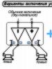
Installation of Volgov gearboxes in “civilian” bridges
The problem of reliability of "collective farm" bridges and reducing their noise can be solved by replacing the gearboxes with Volgovsky ones (Gaz-24). This requires replacing the bridge stockings. But not a complete replacement, but only the part where the gearbox is located. The rest remains UAZ. The whole thing is that the UAZ gearbox rests on two bearings located close to each other. And it turns out that the gearbox on one side seems to be hanging in the air. At the slightest violation of the clearance adjustment, the gearbox begins to become loose, because It turns out that even though there are two bearings, but due to the fact that they are next to each other, there is only one support - like a swing. This results in noisy bridges. The gearboxes are falling apart. The Volgov gearbox also rests on two bearings, but they are spaced along the edges of the gearbox and firmly secure it in the stocking. In addition to reliability, speed also increases. Now you can also install armored personnel carriers. Now they will not fly out as often as happens on their original bridges.
This page contains photos of the interior of the UAZ Bukhanka car:
Location of controls

1 - steering wheel. The steering wheel of UAZ-31512, UAZ-3153 and the UAZ-3741 family vehicles has a central horn button. The steering wheel of UAZ-31514 and UAZ-31519 cars is equipped with an energy-intensive pad and has two horn buttons located in the wheel spokes.
2 — rear view mirror (internal). Adjustable by turning around the articulated head.
3 — instrument panel.
4 — sun visors.
5 — windshield blower pipes.
6 — passenger handrail.
7 — lamp (plafond) lighting.
8 — battery ground switch. Turning the “mass” on and off is done by turning the knob 90°.
9 — lever for engaging the front drive axle. It has two positions: front - the axle is on, rear - the axle is off. Before engaging the front axle, engage the front wheels. Turn on the axle while the vehicle is moving.
10 - heater.
11 — transfer case control lever. It has three positions: forward - direct gear is engaged, middle - neutral, reverse - downshift is engaged. Before downshifting, engage the front axle. Engage the downshift with the clutch disengaged and only when the car is completely stopped.
12 — gear shift lever. The switching pattern is shown on the handle. Shift gears by smoothly pressing the lever without jerking. If you cannot engage the required gear before moving off, lightly release the clutch pedal, and then disengage the clutch a second time and engage the gear. When switching from a higher gear to a lower one, it is recommended to disengage the clutch twice and briefly press the throttle pedal. Engage reverse gear only after the vehicle has come to a complete stop. When you engage reverse, the reversing light turns on.
13 — lever of the parking brake system. To turn the lever on, move it back; to turn it off, press the button at the end of the lever and move the lever forward until it stops. When the parking brake is engaged, the red warning lamp on the instrument panel lights up.
14- handle for driving the hatch cover for ventilation and heating of the body.
15 — valve handle for switching fuel tanks. The handle is turned forward - the valve is closed, turned to the left - the left tank is on, turned to the right - the right tank is on. The valve is not installed on vehicles with one fuel tank.
16 — carburetor throttle control pedal.
17 — pedal of the service brake system. Brake the car smoothly, gradually increasing pressure on the pedal. When braking, do not let the wheels slide, as in this case the braking effect is significantly reduced (compared to rolling braking) and tire wear increases. In addition, strong and sudden braking on a slippery road can cause the car to skid.
18 — clutch pedal. When changing gears and starting from a stop, the clutch pedal should be pressed quickly and fully, and released smoothly. Depressing the pedal slowly or incompletely causes the clutch to slip, making it difficult to shift gears and causing increased wear on the clutch plate. When the pedal is suddenly released (especially when starting from a standstill), the load on the transmission increases, which can lead to deformation of the clutch driven disc and other transmission parts. When driving the car, do not keep your foot on the clutch pedal, as this leads to partial disengagement of the clutch and the disc slipping.
19 — foot switch for headlights. By pressing the button, with the headlights on, the low beam or high beam headlights are turned on. Not installed on vehicles with multifunctional left-hand stalks.
20 - portable lamp socket.
21 — radiator shutter control handle. Under certain operating modes and climatic conditions, in order to maintain the temperature of the engine coolant within 70-80 ° C, it is necessary to regulate the amount of air cooling the radiator using blinds. When the handle is pulled, the blinds close.
22 — rear view mirror (external).
23 — direction indicator switch handle. The handle automatically returns to the neutral position when turning the steering wheel
in the opposite direction (when the car enters the straight line). Some cars are equipped with multifunction steering column switches.
24 - carburetor throttle control knob. The extended handle is fixed by turning 90° in any direction.
25 - carburetor choke control handle. The extended handle is fixed by turning 90° in any direction.


Console:

1 — alarm switch. When you press the switch button, the lamps of all indicators and turn signal indicators, the signal lamp for turning on the turn indicators (item 6) and the indicator lamp inside the switch button simultaneously operate in a flashing mode.
2 — speedometer. It shows the speed of the car in km/h, and the counter installed in it shows the total mileage of the car in km.
3 — fuel level indicator in the tank. Each tank has its own indicator sensor (except for additional tanks).
4 — warning lamp for emergency condition of the brake system (red). Lights up when the tightness of one of the hydraulic drive circuits to the brake mechanisms is broken.
5 - warning light for turning on the parking brake (red).
6 — signal lamp for turning on the direction indicators (green). Operates in flashing mode when the turn signal switch or hazard warning light switch is turned on.
7-signal lamp for emergency overheating of the coolant in the radiator.
8 — signal lamp for turning on the high beam headlights (blue).
9 — coolant temperature indicator in the engine cylinder block.
10-signal lamp for emergency oil pressure. Lights up when the oil pressure in the engine lubrication system drops to 118 kPa (1.2 kgf/cm2)
11 — oil pressure indicator in the engine lubrication system. 12 - voltmeter. Shows the voltage in the vehicle's on-board network.
13 - cigarette lighter. To heat the cigarette lighter coil, press the handle of the insert, push it in until it locks into the body and release the handle. When the required heating temperature of the spiral is reached, the insert automatically returns to its original position. Forced holding of the insert in a recessed position is not allowed.
14 — lighting lamp (installed on UAZ-31512, on other models a courtesy lamp is installed)
15 - lighting switch. On some models the switch is located next to the lampshade.
16 — carburetor throttle control knob.
17 — switch for fuel level sensors in tanks.
18 - rear fog lamp switch with built-in warning light
19 — fog lamp switch.
20 - combined ignition and starter switch (see Fig. 1.22 and 1 23). The key from the ignition switch of UAZ-31514, UAZ-31519, UAZ-3153 vehicles is removed only in position III, and the locking mechanism is activated, blocking the steering shaft. To lock the steering when parked, set the key to position III, remove it and turn the steering wheel in any direction until you hear a click, indicating that the tongue of the locking device coincides with the groove of the steering wheel shaft locking sleeve. When unlocking the steering, insert the key into the ignition switch and, rocking the steering wheel left and right, turn the key clockwise to position 0. In order to eliminate cases of erroneous activation of the starter while the engine is running (key position II), a lock is used in the design of the ignition switch mechanism , making it possible to restart the engine only after returning the key to position 0.
If gear shifting is harsh or imprecise, it may be due to the shift linkage. In this case, it is recommended to remove the gear shift rod, check for wear and damage, and after lubricating all the hinge joints, install the rod in place. On some early model cars, the length of the shift rod can be adjusted if necessary. However, this adjustment is intended for the initial installation of the rod (when replacing the rod with a new one or if the length of the rod does not correspond to the norm) and is not intended to compensate for wear during operation.
| EXECUTION ORDER | |||
|
UAZ (loaf) cars have the most spacious body. The machine body is made of durable material. The vehicle is equipped with security systems, a durable power unit that is capable of developing more than 100 horsepower, and a transmission system.
The all-wheel drive cargo-passenger UAZ, which has increased cross-country ability, began to be mass-produced at the Ulyanovsk Automobile Plant in the mid-1960s.
The new UAZ 452 family vehicles have a manual transmission (four-speed). Inertial type synchronizers provide easier gear shifting. The five-speed ADS gearbox is synchronized in all forward gears.

The UAZ can be equipped with a 5-speed manual transmission Daimos (DYMOS). This gearbox is distinguished by its reliability. Its average service life is 300,000 km. The filler plug is located in the middle of the box, the drain is at the bottom. It seems possible to unscrew them using a hex key. When oil is drained, special containers should be prepared. New fluid must be filled to the level of the oil filler hole on the box. The dipstick allows you to accurately determine to what level the liquid is filled. An alternative to the probe can be a long nail. For preventive purposes, the oil level must be measured every 15,000 km.
The presence of mechanics on this version of the vehicle is completely justified. It is important to use such a car on rough terrain and off-road. In addition to this, there will be no problems with towing.
The gearbox has external shift levers. The lever in the cabin moves freely both parallel and perpendicular to its axis.
The machine is equipped with a transfer case. The design of the transfer case for the UAZ 452: drive axle shafts, gears. All of the listed components are located in a cast iron crankcase. The crankcase and the cover are connected with nuts. The shift fork rods are securely fixed in the cover.
There is a spline and bearings. There is a helical gear for the speedometer drive. The intermediate shaft is fixed to the “loaf” bearings. This box has reliable gears with straight teeth.
Thus, the gearbox on the UAZ 452 consists of many components and assemblies. This unit requires regular maintenance.


The need to diagnose the UAZ model 452 gearbox
This vehicle must be diagnosed if control begins to deteriorate, characteristic creaks are heard when a gear change occurs, or gears begin to change spontaneously. The UAZ transfer case should be checked if the grip of the wheels on the road has noticeably deteriorated, a hum or increasing noise has begun to appear during its operation.
During maintenance, technicians must check the system for oil leaks and lubricant levels. All worn parts in the transmission system must be replaced with new ones. Also, diagnostics involves lubricating the lever axle and adjusting the front linkages.
Routine diagnostics in a professional auto repair shop allows you to accurately determine the existing nature of the problem with the gearbox and eliminate existing problems at an early stage.
Causes of breakdowns
As a rule, the need to replace the main components of a gearbox arises due to their natural wear and tear.
Causes of gearbox breakdowns
The main reason for oil leakage from the gearbox is the presence of an increased level of fuel in the system. For UAZ gearboxes, you should use high-quality oil. If the liquid is not of the proper quality, this may cause characteristic noises from the box. When the synchronizer or its parts wear out, it is always difficult to change gears. You should also pay attention to the details of the switching mechanism. When gear teeth are deformed, gears often switch off automatically.
Transmission removal process
It is quite possible to repair the gearbox on a UAZ 452 yourself. This requires:
- a set of wrenches, including the keys needed to tighten the nuts;
- screwdrivers;
- hammer;
- chisel;
- pliers.
Dismantling algorithm.
The car must be parked on level ground. It is necessary to drain the oil from the two boxes by unscrewing the drain plugs. Next, the front seats, hatch halves, clutch release fork, transverse frame, and gear shift levers are removed.
The speedometer shaft, suspension supports in the chassis, and brake system levers must be removed. As a result, the exit to the clutch housing opens. The box is fixed on it with fastening nuts, which must be unscrewed, then the UAZ gearbox along with the transfer gearbox is carefully pulled out until the spline shaft exits the flywheel. The driver will need an assistant to remove the box.
Assembling a UAZ gearbox requires due attention. During self-assembly, the driver may have difficulty installing the input shaft into the clutch system. During this process, it is necessary to actively move the box so that the shaft gets into the splines.
As soon as disassembly into individual component parts has occurred, the box must be washed in kerosene and dried. All spare parts are checked for integrity. First of all, this concerns the crankcase and shafts. If the threads on the shafts are damaged, they need to be replaced. It seems dangerous to operate the machine if there are chips on the gears.
Thus, timely repair of the UAZ “loaf” gearbox helps to extend the service life of the gearbox.
Transmission components for UAZ-3962, UAZ-3741 vehicles
Maintenance of the UAZ-3962, UAZ-3741 gearbox
During operation, check the oil level in the UAZ-3962, UAZ-3741 gearbox and replace it within the time limits specified in the lubrication table. If a leak is detected, find out the cause and replace the faulty parts (gaskets, plugs, etc.).
Periodically check the fastening of the gearbox, as well as the fastening and adjustment of the gearbox control mechanism.
The tightening torque of the bolts and nuts securing the gearbox to the clutch housing and transfer case should be from 39 to 55 Nm (4.0-5.6 kg/cm)
Removing the UAZ-3741, UAZ-3962 gearbox
Removing the UAZ-3962, UAZ-3741 gearbox is carried out in the following order:
Drain the oil from the gearbox and transfer case.
Remove the clutch release fork.
Remove the clutch release bearing grease cap and disconnect it from the bearing lubrication hose.
Disconnect the shift rods from the shift mechanism and transfer case.
Support the engine from below using a jack or other device.
Unscrew and disassemble the rear engine mounts.
Disconnect the driveshaft flanges.
Disconnect the parking brake cable.
Disconnect the speedometer flex shaft.
Remove the four nuts securing the gearbox to the clutch housing.
Move the unit back until the input shaft of the UAZ-3741, UAZ-3962 gearbox exits the clutch housing.
Lower the unit down.
Dismantling the synchronized gearbox UAZ-3962, UAZ-3741
Disassemble the synchronized gearbox UAZ-3962, UAZ-3741 in the following order:
Remove the side cover with the switching mechanism.
Using the M8 threaded hole in the rear end of the reverse idler gear axle, press the axle back and remove the gear.
Remove the input shaft bearing cap.
Remove the front intermediate shaft bearing cover.
Unscrew the rear intermediate shaft bearing mounting bolt (the bolt has a left-hand thread) and remove the bolt's disc spring.
Using a puller, remove the rear bearings of the primary and secondary shafts by their retaining rings.
Remove the retaining ring of the rear bearing of the intermediate shaft of the UAZ-3962, UAZ-3741 gearbox.
Install the box so that the intermediate shaft is at the top, move the intermediate shaft forward until the intermediate shaft gear block stops in the crankcase.
Move the intermediate shaft along with the rear bearing back until the inner race of the front bearing comes out of the rollers and the rear bearing comes out of the crankcase.
Remove the rear intermediate shaft bearing using a puller.
Install the UAZ-3741, UAZ-3962 gearbox with the hatch under the shift mechanism facing upwards.
Remove the input shaft, 4th gear locking ring, secondary shaft assembly (supporting the 1st gear spacer ring) and intermediate shaft assembly from the transmission housing.
Disassembling the gearshift mechanism of the UAZ-3962, UAZ-3741 gearbox
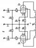
Rice. 3. Gear shift mechanism for UAZ-3962, UAZ-3741 vehicles
1-reverse fork rod; 2-reverse fork; 3-rod fork for selecting III and IV gears; 4-fork III and IV gears; 5-fork 1st and 2nd gears; 6-rod fork for 1st and 2nd gears; 7- cotter pin wire; 8 - plug; 9-washer; 10-shaft gear shift; 11-side cover; 12-gear clutch; 13-locking spring; 14-gasket; 15-oil seal cover; 16-shift lever; 17-cork; 18,20-clamp springs; 19-key plunger; 21-ball retainer; 22-gear selection lever; 23-selective lever; 24-pin; 25-reversing light switch; 26-plug
Disassemble the gear shift mechanism (Fig. 3) in the following order:
Remove the three plugs for the rod holes in one of the ends of the cover.
Undo the cotter pins and turn out the locking screws of the UAZ-3962, UAZ-3741 gearbox forks.
Unscrew the plug of the rod lock socket for 1st and 2nd gears and remove the spring and lock ball.
Press the rods through the holes in the cover where the plugs were removed and remove the forks. When pressing out the rods of the 3rd and 4th gears and reverse gear, do not lose the retainer ball, which is ejected by the spring.
- Remove the springs and balls of the UAZ-3962, UAZ-3741 gearbox rod clamps; remove the two lock plungers through the hole in the 1st and 2nd gear lock.
Unscrew the nut and remove lever 22 from the splines (see Fig. 3).
Knock down the pin 24 securing the lever axis 23 and remove the axis together with the selection lever.
Unscrew the nut and remove lever 16.
Unscrew the three bolts, remove the oil seal cover 15 and remove the spring. Having lowered shaft 10 with coupling 12 and two washers, remove the shaft through the side cavity of the cover.
Before removing levers 22 and 16, note the relative position of the levers on the rollers in order to install the levers in their previous position.
Disassembling the gear shift control mechanism of the UAZ-3962, UAZ-3741 gearbox

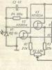
Rice. 4. Gear shift control mechanism for UAZ-3962, UAZ-3741 vehicles
1-gear shift lever; 2-mechanism seal; 3-select lever mechanism; 4-switch lever mechanism; 5-vertical shift rod; 6-intermediate shift lever; 7-intermediate selector lever; 8-horizontal pull rod selection; 9-gear shift lever; 10-gear selection lever; 11-horizontal shift rod; 12-arm intermediate bracket; 13-intermediate selector lever; 14-vertical selection rod; 15-grease nipples
Disassemble the gear shift control mechanism in the following order:
Disconnect rods 8 and 11 (Fig. 3) from levers 9 and 10.
Unscrew rods 5 and 14 from levers 6 and 13.
Disconnect the bracket 12 intermediate levers of the UAZ-3962, UAZ-3741 gearbox.
Remove the mechanism bracket together with gear shift lever 1.
Wash the control mechanism parts.
By external inspection, identify wear in the levers and rods.
Replace worn parts.
Assembling the gearbox shift mechanism UAZ-3962, UAZ-3741
Assemble the gear shift mechanism in the following order:
Install the rubber O-ring into the shift shaft oil seal cover.
Install the rubber sealing ring into the hole under the axis of the selective lever 23 (see Fig. 3).
Install the clutch, thrust washer, spring retainer and spring onto the shift shaft. Insert the shaft into the side cover body and install the oil seal cover with the gasket, secure the cover with three bolts.
Install the selector lever and axle assembly into the cover body so that the lever fits into the groove of the shift clutch. Lock the lever with a pin, which is driven in from below.
Turn the side cover over with the machined flange up and insert the springs and balls of the rod of III and IV gears and the reverse rod of the UAZ-3741, UAZ-3962 gearbox into the sockets of the retainers using a mandrel.
Install the reverse fork onto the rod on the side opposite to the lock, and, having pressed the ball of the lock into the cover body using a mandrel, set the rod to the neutral position. So, assemble all the rods and forks in sequence. Install locking blocks between the rods.
Secure the forks to the rods with conical bolts and pin them with wire, which should not interfere with the movement of the forks. When attaching the forks, the shift clutch lever must be in the groove of the forks.
Insert the ball and the retainer spring into the hole in the rod of the 1st and 2nd gears and tighten the plug. Please keep in mind that the rod lock spring for 1st and 2nd gears in the free state is longer than the other two rod lock springs.
Install six plugs into the end holes of the cover body, a plug into the hole for the shift shaft and hammer them out.
Install the selector and shift levers onto the shaft splines and secure them with nuts and spring washers.
The correct position of the levers is checked with the gears in the neutral position in the gearbox after installing the shift mechanism on the gearbox.

Fig.5. Position of the selection lever and shift lever after installing the mechanism on the UAZ-3962, UAZ-3741 gearbox
A-corresponding to reverse; B-corresponding to the inclusion of III and IV gears; B-corresponding to the inclusion of 1st and 2nd gears; 1-selection lever; 2-shift lever (in neutral position)
Assembly and adjustment of the gearshift control mechanism of the UAZ-3962, UAZ-3741 gearbox
Assemble the gear shift control mechanism in the reverse order of disassembly. After assembly, adjust the gearbox control mechanism.
Adjust the UAZ-3962, UAZ-3741 gearbox by changing the length of the horizontal rods - 8.11 (see Fig. 4) and vertical rods - 5.14 in the following order:
Before starting the adjustment, set lever 9 to the neutral position (N), and lever 10 to position III-IV until it stops against the locking spring.
Place gear shift lever I in the position corresponding to the selection of gears I and II. In this position, connect and secure selection rods 8 and 14, preventing the levers from being pulled up.
After this, place lever 1 in the position corresponding to the selection of gears III and IV and also freely connect shift rods 5 and 11.
After completing the adjustment, check that the gears are fully engaged. To do this, engage first gear and make sure that the rods and levers do not rest against adjacent parts. Perform the same check with reverse gear engaged.
In this case, make sure that the intermediate lever 6 does not rest against the frame cross member and the mudguard. When reverse is engaged, the gap between them should be 2-3 mm.
_____________________________________________________________________________
_____________________________________________________________________________
_____________________________________________________________________________
_____________________________________________________________________________
UAZ-469, 31512, 31514
_____________________________________________________________________________
_____________________________________________________________________________
UAZ-3160 Simbir
UAZ-3303, 452, 2206, 3909