Voltmeter with extended scale. Pointer voltmeter How to make a voltmeter with a stretched scale
How to make a new scale for a dial gauge October 27th, 2015
I don’t yet know what kind of modding project this measuring head will be used in, so I decided to write a separate post about it. I am posting the information hot on the heels, literally and figuratively: successful technology was found only yesterday.
So, in my household I had an old M24 series dial gauge, calibrated as a millivoltmeter/milliammeter. From a functional point of view it was serviceable, but the scale had clearly seen better days, so it was no longer suitable for my purposes.
Previously, when people asked me why I didn’t change instrument scales in my mods, marked in some extraneous quantities, I answered that I didn’t want to spoil the original old things. And this was true, but only half: the fact is that even if I wanted to change some scale to a new one, I would not know how to do it efficiently.
I made my first attempt to adapt this device for use in conjunction with a computer several years ago, when, based on a scan of the original scale, I drew my own and printed it on old paper.
The scale, frankly speaking, came out very poorly. It looked ugly, the yellow color of the paper did not match the other details, and the division price in the lower part of it turned out to be fractional.
Therefore, I did not use this device anywhere and put it in a drawer for a long time. But recently I took it out of there and decided to do everything right this time. First of all, I connected it to a voltage source and accurately calibrated it, putting pencil marks from 0 to 100 (it was decided to mark one of the scales as a percentage in order to use it to display a wide variety of values).
I then removed the timeline and scanned it.
I wanted the new scale to look nice and authentic. So I dug through a drawer of old pointer heads and found one that I liked best.
Using various Photoshop tools, I removed as much of the original background as possible and superimposed the resulting image on top of the scan with pencil marks. By a happy coincidence, it turned out that it was enough to just scale the new scale a little so that it perfectly matches the drawn one. Apparently, the devices have the same type of mechanisms with a nonlinear dependence of the angle of deviation on the voltage - if you look closely at the scale, you will notice that the interval from 0 to 1 is noticeably larger than the interval from 9 to 10.
The following picture shows an intermediate stage of work: some of the numbers are still missing, some areas have not been redrawn, and uncollected “garbage” is visible.
In order for the device to end up looking as close to the real thing as possible, I did not use characters from new fonts, but only copied the original ones. If I had to use the same number twice, I deliberately deformed it a little so that there would not be a perfect digital copy. This kind of pedantry may not be very healthy :-). The debris had to be removed manually, because I do not know of an automatic cleaning mechanism that would remove the dust without blurring the contours.
In the end it turned out like this:
The first scale displays percentages, the second - temperature (calibrated according to the temperature sensor datasheet, which does not guarantee the accuracy of readings below zero), and the third - processor frequency in megahertz. I left the nostalgic value “IMP / MIN” because, as they say, it is on topic. Due to the gradual compaction of the divisions, the marks on the temperature scale turned out to be very small, but it was decided to ignore this. At the very end I added an outline of the metal backing to make the scale easy to cut out and place in place.
It was possible to remove the inscriptions from the original scale using ordinary soap. If soap does not help, you can try alcohol, acetone, solvent 646, acetic acid or hydrogen peroxide - in my practice there has never been a case when this “cocktail” did not work.
But this was all just a prelude, the real witchcraft is yet to come. I didn’t even consider printing the new scale on paper, but instead began to think about how to apply the inscriptions directly onto the original aluminum plate. The easiest thing, of course, would be to load it into an inkjet printer converted for printing on hard surfaces (some cool radio amateurs make these for making printed circuit boards), but this option had to be discarded due to the lack of a suitable printer. I also remembered such a thing as metal printing, but it also requires special equipment, and I wanted to find a method that I could use at home.
Therefore, it was decided to master another technology from the arsenal of radio amateurs - LUT (“laser-ironing”). It has been described so many times on the Internet that I see no point in repeating it. In short, a design is printed using a laser printer on some smooth paper in a mirror image, after which it is transferred to the desired surface using heat. This method is used to create tracks on printed circuit boards, but in my case the last technological stage - etching - was not needed.
I haven’t used LUT before, so I decided to practice on cats first. After reading many recommendations, I chose two intermediate media - semi-gloss magazine pages and photo paper of unknown origin.
Photo paper didn't work because its glossy coating melted under the iron, but magazine pages worked just fine.
To check, I first tried to transfer the design onto foil PCB to make sure that the technology was followed correctly. The result exceeded all expectations: the first time the drawing was transferred to copper without any defects.
However, before this, the surface had to be carefully prepared: remove oxides using Cillit Bang, wash with soap and degrease with gasoline.
Inspired by this success, I tried to transfer the scale onto a rough aluminum plate. And here I was disappointed: although I did everything exactly the same as last time, a significant part of the toner remained on the paper.
No matter how hard I tried, I was unable to improve this result. Aluminum, as far as I know, is generally a very capricious metal in this regard - paint adheres worse to it and other coatings that are not applied chemically.
True, some hope for success was inspired by the fact that the basis of the future scale was not smooth, but embossed. This can be clearly seen in the scan with an enlarged fragment:
Not being sure of a successful outcome, I decided to purchase transparent film for laser printing, so that if something happened, I could simply print the scale on it and put it on top. The pack of this film had been lying unclaimed in the store for so long that it had turned yellow and frayed. The seller was very surprised that someone finally bought it.
On the left in the photo is a scale printed on plain paper, which I used to check that the needle was reading correctly one last time. And on the right is the film, face down (the printing is done in a mirror image so that the toner is protected).
I tried simply placing the scale on the backing - it looked good, but only as long as the film remained perfectly flat. But when I stopped pressing it, it moved away from the base, and the view immediately deteriorated. So I took to the iron, initially planning to simply heat the plate and film so that the latter would straighten out and perhaps fuse a little to the base.
It really worked out, and I wanted to leave it that way, but curiosity still got the better of me. I tried to “attach” the second copy of the scale to another sheet of aluminum, and, to my surprise, the drawing was transferred with minimal loss, although the surface was completely unprepared! So I went back to my scale, ironed the top properly, let it cool, carefully peeled off the film... and voila, 99% of the toner was safely transferred to the substrate!
In the center of the scale you can see a slightly blurry area - there was a gap there, and I rather crookedly painted on the missing fragments with a gel pen. At first it seemed to me that it would be unnoticeable, but the defect was an eyesore, so the next day I washed off the scale with solvent 646 and did all the operations again, only without extra steps and old mistakes. The end result was almost perfect:
I think that I will gradually get better at it, and then almost limitless possibilities will open up for making all kinds of scales and other drawings and inscriptions that look like factory ones. It will even be possible to make them in color if printed on an appropriate printer.
P.S. After re-reading the text, I realized that what I got was not a guide from a master, but rather a scene from the movie “Cast Away,” where Tom Hanks’ character admires the first fire made :-). But I hope that this post will still be useful to someone.

In order to measure the voltage of a car battery, a digital device is usually used, since a conventional pointer does not allow this to be done with the required accuracy - after all, an error of even a few tenths of a volt can lead to an incorrect assessment of the condition of the battery or the operation of the generator.
On the other hand, to monitor the battery voltage, you don’t need a large part of the scale, since you have to measure the voltage in a fairly narrow range - 10 ... 15 V. Thus, if you stretch the scale to measure only in the specified interval, then the pointer device will not cope with the task worse than the much more expensive digital one. Today we will build just such a voltmeter.
The circuit diagram of a voltmeter operating in the range of 10...15 V is a bridge, the diagonal of which includes a microammeter with a total deviation current of 50 μA (for example, M1690A). One arm of the bridge includes a zener diode VD1 with a current-limiting resistor R1, and the other arm includes a divider consisting of resistors R3, R4, R5. Resistor R2 is used to set the measurement range. Switch S1, which in the “Transportation” mode short-circuits head PA1 and prevents the pointer from oscillating when shaking, serves for safe transportation of the device. In place of VD1, instead of the one indicated in the diagram, D818 with any letter designation can work, and as PA1 - any microammeter with a total deviation current of 50 ... 100 μA. It makes sense to use multi-turn resistors R2 and R5 (for example, SP3-36 and SP5-2V).

Resistors of the type SP3-36 of the nominal value we need were widely used in electronic channel selectors of 3rd-4th generation TVs produced in the USSR
Since the scale of our device is almost linear, it can be calibrated before setting it up by setting the value 10 V at the beginning, and 15 V at the upper limit. We evenly calibrate the entire scale between these values with the required accuracy.
To set up the device, you will need an adjustable power supply with a voltage of 0 ... 15 V and a control voltmeter with the highest possible measurement accuracy. Setting up the device is carried out in the following sequence:
1.
We connect the power supply to the terminals of our device (X1 and X2) and gradually increase the voltage to 10 V, constantly monitoring it using a standard voltmeter.
2.
At a voltage of 10 V, by adjusting the resistor R5, we set the arrow of the PA1 measuring device to the zero mark.
3.
We increase the voltage to 15 V and by adjusting the resistor R2 we set the pointer of the PA1 device to the end mark of the scale.
If necessary, repeat steps 2 and 3 several times, and if the upper and lower readings of the device are accurate, the adjustment can be considered complete. We apply a drop of paint or any varnish to the adjusting screws, and place the circuit itself in a shock-resistant case of suitable dimensions.
Share to:The device will be useful to car enthusiasts for measuring battery voltage with high accuracy, but it can also find other applications. 4.6 Voltmeter with an extended scale where it is necessary to control the voltage in the range of 10...15 V with an accuracy of 0.01 V. It is known that the degree of charge of a car battery can be judged by its voltage. So, for a completely discharged, half-discharged and fully charged battery, it corresponds to 11.7, 12.18 and 12.66 V. In order to measure the voltage with such accuracy, you need either a digital voltmeter or a dial voltmeter with an extended scale, which allows you to control the voltage of interest to us interval. The diagram shown in Fig. 4.6, allows, using any microammeter with a scale of 50 μA or 100 μA, to make it into a voltmeter with a measurement scale of 10...15 V. The voltmeter circuit is not afraid of incorrect polarity connection to the measured circuit (in this case, the readings of the device will not correspond to the measured value ). To protect the PA1 microammeter from damage during transportation, switch S1 is used, which, when the leads of the measuring device are short-circuited, prevents the needle from oscillating. The circuit uses a PA1 device with a mirror scale, type M1690A (50 μA), but many others are also suitable. Precision zener diode VD1 (D818D) can be with any last letter in the designation. It is better to use multi-turn trimmers, for example R2 type SPZ-36, R5 type SP5-2V. To configure the circuit, you will need a power supply with an adjustable output voltage of O...15 V and a standard voltmeter (it is more convenient if it is digital). The setting consists of connecting the power supply to terminals X1, X2 and gradually increasing the voltage to 10 V, using resistor R5 to achieve the “zero” position of the arrow of the PA1 device. After this, we increase the voltage of the power source to 15 V and use resistor R2 to set the arrow to the limit value of the measuring device scale. At this point, the setup can be considered complete.
 Rice. 4.7. Circuit for more accurate measurement of mains voltage Based on this circuit, the device can be made multifunctional. So, if the microammeter leads are connected to the circuit via a 6P2N switch, you can make it a regular voltmeter by selecting an additional resistor, as well as a tester for checking circuits and fuses. The device can be supplemented with a circuit (Fig. 4.7) for measuring alternating mains voltage. In this case, its scale will be from 200 to 300 V, which allows you to more accurately measure the mains voltage. Chapter:
 Voltmeter - electrical dictionary starting with the letter B
A voltmeter is an electrical device that is designed to measure the EMF, read voltage, of a section of an electrical circuit. A voltmeter in an electrical circuit is designated by a circle containing the Latin letter V or Russian V, which is read as “volt”. In honor of the famous scientist Alessandro Volta.
Thus, a voltmeter measures voltage in units of volts
Continuing the theme of history, we can say that the first analogue of a voltmeter was invented by the Russian scientist G.V. Richman. in the 18th century. That device was called an “electric force indicator” and its operating principle is still based on the operation of an electrostatic voltmeter.
How a voltmeter is connected to a circuit
The voltmeter is connected to the circuit parallel to the section of the circuit being measured. Below is a simple diagram for connecting a voltmeter to a circuit and a diagram for connecting it through an instrument transformer.

Types of voltmeters
Voltmeters have a wide range of types, depending on the operating principle and area of application.
By measured voltage class
- - nanovoltmeter (for measuring ultra-low voltages, up to 1nV, and can be used for scientific and metrological purposes)
- - microvoltmeter
- - millivoltmeter
- - voltmeter (12, 24, 30, 100, 220, 300, 500 V)
- - kilovoltmeter (to determine voltage values of the order of units to tens of kilovolts, can be used when testing high-voltage equipment)
- - vectormeter (a device that measures current, voltage and phase angle and can be used when testing the magnetic properties of steels and laboratory studies of complex circuits and devices)
- - selective voltmeters are used to measure alternating voltage in the frequency range from 20 Hz to 35 MHz, according to GOST 9781-85
According to the operating principle
(the principle of operation of a voltmeter is similar to the principle of operation of an ammeter, which is described in detail at the link)
- - electromechanical voltmeters
- - magnetoelectric Mxx (this type of voltmeter is quite accurate and has high sensitivity, however, the readings are strongly influenced by the shape of the voltage curve and are used only for DC circuits)
- - electromagnetic Exx (used as panel devices, easy to manufacture, consume about 5 W of power and their readings are highly dependent on frequency)
- - electrodynamic Dxx (the most accurate, measure the effective value of direct and alternating current voltage)
- - electrostatic Cxx (used to measure high voltages of constant and variable magnitude)
- - rectifier (measurement of low frequency voltages)
- - thermoelectric Txx (have low input resistance and low overload capacity)
- - electronic Фxx, Шxx
- - analog
- - digital
By purpose
- - direct current
- - alternating current
- - pulse
- - phase sensitive
- - selective
- - universal
By design
- - panel
- - portable
- - stationary
Voltmeter with stretched scale

An extended scale voltmeter circuit will allow you to measure small voltage deviations (delta U) relative to the input voltage. For an ordinary voltmeter this task is not easy.
Where can a stretched scale voltmeter circuit be used?
- - supply voltage control
- - voltage control on control equipment
- - assessment of battery discharge
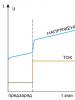
With the help of zener diode D1, the working section of the voltmeter scale expands. The threshold voltage of zener diode D1 will be UCT = U - DU. When the input voltage reaches the threshold value, the zener diode breaks through. The current through the zener diode increases, but the voltage does not change much. The second counter zener diode D2 is switched on counter and this switching allows to reduce temperature instability.
The input voltage is divided between resistor R and the zener diodes. Since the voltage drop across the zener diodes remains unchanged, the voltage drop across the resistor will be equal to the difference between the input voltage and the zener diode voltage.
The resistor resistance is determined as R=2ДU/Ist.max
where 2ДU is the measurement limit of the device, Istabilization current
The device will be useful to car enthusiasts for measuring the voltage on the battery with high accuracy, but it can also find other applications where it is necessary to control the voltage in the range of 10...15 V with an accuracy of 0.01 V.
Rice. 1 Voltmeter with extended scale
It is known that the degree of charge of a car battery can be judged by its voltage. So, for a completely discharged, half-discharged and fully charged battery it corresponds to 11.7, 12.18 and 12.66V.
In order to measure voltage with such accuracy, you need either a digital voltmeter or a dial voltmeter with an extended scale, which allows you to control the interval of interest to us.
The diagram shown in Fig. 1, allows, using any microammeter with a scale of 50 μA or 100 μA, to make it into a voltmeter with a measurement scale of 10...15 V.
The voltmeter circuit is not afraid of incorrect polarity connection to the measured circuit (in this case, the device readings will not correspond to the measured value).
To protect the microammeter PA1 from damage during transportation, switch S1 is used, which prevents the needle from oscillating when the leads of the measuring device are short-circuited.
The circuit uses a PA1 device with a mirror scale, type M1690A (50 μA), but many others are suitable. Precision zener diode VD1 (D818D) can have any last letter in the designation. It is better to use multi-turn tuning resistors, for example R2 type SPZ-36, R5 type SP5-2V.
To set up the circuit, you will need a power supply with an adjustable output voltage of O...15 V and a standard voltmeter (it is more convenient if it is digital). The setting consists of connecting the power supply to terminals X1, X2 and gradually increasing the voltage to 10 V, using resistor R5 to achieve the “zero” position of the arrow of the PA1 device. After this, we increase the voltage of the power source to 15 V and use resistor R2 to set the arrow to the limit value of the measuring device scale. At this point, the setup can be considered complete.

Rice. 2. Circuit for more accurate measurement of mains voltage
Based on this diagram, the device can be made multifunctional. So, if the microammeter leads are connected to the circuit via a 6P2N switch, you can make it a regular voltmeter by selecting an additional resistor, as well as a tester for checking circuits and fuses.
The device can be supplemented with a circuit (Fig. 2) for measuring alternating mains voltage. In this case, its scale will be from 200 to 300 V, which allows you to more accurately measure the mains voltage.
List of radioelements
| Designation | Type | Denomination | Quantity | Note | Shop | My notepad | |
|---|---|---|---|---|---|---|---|
| VD1 | Zener diode | D814D | 1 | To notepad | |||
| R1, R3, R4 | Resistor | 270 Ohm | 3 | 1 Watt | To notepad | ||
| R2 | Trimmer resistor | 100 kOhm | 1 | To notepad | |||
| R5 | Trimmer resistor | 2.2 kOhm | 1 | To notepad | |||
| PA1 | Microammeter | М1690А | 1 | To notepad | |||
| S1 | Switch | 1 | To notepad | ||||
| VD1-VD4 | Diode | KD243Zh | 4 | To notepad | |||
| R1 | Resistor | 12 kOhm | 1 | 2 Watt | |||