DIY electronic digital voltmeter. Just about something complicated: how to make a car voltmeter with your own hands? Voltage converter LT1308
When working with various electronic products, there is a need to measure the modes or distribution of alternating voltages on individual circuit elements. Conventional multimeters turned on in AC mode can only record large values of this parameter with a high degree of error. If you need to take small readings, it is advisable to have an AC millivoltmeter that allows you to take measurements with an accuracy of millivolts.
In order to make a digital voltmeter with your own hands, you need some experience working with electronic components, as well as the ability to handle an electric soldering iron well. Only in this case can you be sure of the success of assembly operations carried out independently at home.
Microprocessor based voltmeter
Parts selection
Before making a voltmeter, experts recommend carefully studying all the options offered in various sources. The main requirement for such selection is the extreme simplicity of the circuit and the ability to measure alternating voltages with an accuracy of 0.1 Volt.
An analysis of many circuit solutions has shown that for self-manufacturing a digital voltmeter, it is most advisable to use a programmable microprocessor of the PIC16F676 type. For those who are new to the technique of reprogramming these chips, it is advisable to purchase a chip with ready-made firmware for a homemade voltmeter.
When purchasing parts, special attention should be paid to choosing a suitable indicator element on LED segments (the option of a standard pointer ammeter in this case is completely excluded). In this case, preference should be given to a device with a common cathode, since the number of circuit components in this case is noticeably reduced.
Additional Information. Conventional purchased radioelements (resistors, diodes and capacitors) can be used as discrete components.
After purchasing all the necessary parts, you should proceed to wiring the voltmeter circuit (making its printed circuit board).
Preparing the board
Before making a printed circuit board, you need to carefully study the circuit of the electronic meter, taking into account all the components on it and placing them in a place convenient for desoldering.

Important! If you have available funds, you can order the production of such a board in a specialized workshop. The quality of its execution in this case will undoubtedly be higher.
After the board is ready, you need to “stuff” it, that is, place all the electronic components (including the microprocessor) in their places, and then solder them with low-temperature solder. Refractory compounds are not suitable in this situation, since they will require high temperatures to heat them up. Since all the elements in the assembled device are miniature, their overheating is extremely undesirable.
Power supply (PSU)
In order for the future voltmeter to function normally, it will need a separate or built-in DC power supply. This module is assembled according to the classical scheme and is designed for an output voltage of 5 Volts. As for the current component of this device, which determines its calculated power, half an ampere is quite enough to power the voltmeter.
Based on these data, we prepare ourselves (or send it to a specialized workshop for manufacturing) a printed circuit board for the power supply.
Note! It would be more rational to prepare both boards at once (for the voltmeter itself and for the power supply), without spacing these procedures out over time.
When manufactured independently, this will allow you to perform several similar operations at once, namely:
- Cutting blanks of the required size from fiberglass sheets and cleaning them;
- Making a photomask for each of them with its subsequent application;
- Etching these boards in a ferric chloride solution;
- Stuffing them with radio components;
- Soldering of all placed components.
In the case when boards are sent for manufacturing on proprietary equipment, their simultaneous preparation will also allow you to benefit both in price and in time.
Assembly and configuration
When assembling a voltmeter, it is important to ensure that the microprocessor itself is installed correctly (it must already be programmed). To do this, you need to find the marking of its first leg on the body and, in accordance with it, fix the product body in the mounting holes.
Important! Only after you have complete confidence in the correct installation of the most important part, you can proceed to soldering it (“fitting on solder”).
Sometimes, to install a microcircuit, it is recommended to solder a special socket under it into the board, which significantly simplifies all working and configuration procedures. However, this option is beneficial only if the socket used is of high quality and ensures reliable contact with the legs of the microcircuit.
After soldering the microprocessor, you can fill and immediately place all other elements of the electronic circuit on the solder. During the soldering process, the following rules should be followed:
- Be sure to use an active flux that promotes good spreading of liquid solder over the entire landing area;
- Try not to hold the tip in one place for too long, which will prevent overheating of the mounted part;
- Upon completion of soldering, be sure to wash the printed circuit board with alcohol or any other solvent.

If no errors were made when assembling the board, the circuit should work immediately after connecting power to it from an external source of stabilized voltage of 5 Volts.
In conclusion, we note that your own power supply can be connected to the finished voltmeter after completing its configuration and testing, carried out according to standard methods.
Video
We consider simple circuits of digital voltmeter and ammeter, built without the use of microcontrollers on the CA3162, KR514ID2 microcircuits. Typically, a good laboratory power supply has built-in instruments - a voltmeter and an ammeter. A voltmeter allows you to accurately set the output voltage, and an ammeter will show the current through the load.
Old laboratory power supplies had dial indicators, but now they should be digital. Nowadays, radio amateurs most often make such devices based on a microcontroller or ADC chips like KR572PV2, KR572PV5.
Chip CA3162E
But there are other microcircuits of similar action. For example, there is a CA3162E microcircuit, which is designed to create an analog value meter with the result displayed on a three-digit digital indicator.
The CA3162E microcircuit is an ADC with a maximum input voltage of 999 mV (with readings “999”) and a logic circuit that provides information about the measurement result in the form of three alternately changing binary-decimal four-bit codes on a parallel output and three outputs for polling the bits of the dynamic circuit indication.
To get a complete device, you need to add a decoder to work on a seven-segment indicator and an assembly of three seven-segment indicators included in the matrix for dynamic display, as well as three control keys.
The type of indicators can be any - LED, fluorescent, gas-discharge, liquid crystal, it all depends on the circuit of the output node on the decoder and keys. It uses LED indication on a display consisting of three seven-segment indicators with common anodes.
The indicators are connected according to a dynamic matrix circuit, that is, all their segment (cathode) pins are connected in parallel. And for interrogation, that is, sequential switching, common anode terminals are used.
Schematic diagram of a voltmeter
Now closer to the diagram. Figure 1 shows a circuit of a voltmeter that measures voltage from 0 to 100V (0...99.9V). The measured voltage is supplied to pins 11-10 (input) of microcircuit D1 through a divider on resistors R1-R3.
The SZ capacitor eliminates the influence of interference on the measurement result. Resistor R4 is used to set the instrument readings to zero; in the absence of input voltage, and resistor R5 is used to set the measurement limit so that the measurement result corresponds to the real one, that is, we can say that they calibrate the device.
Rice. 1. Schematic diagram of a digital voltmeter up to 100V on SA3162, KR514ID2 microcircuits.
Now about the outputs of the microcircuit. The logical part of the CA3162E is built using TTL logic, and the outputs are also with open collectors. At the outputs “1-2-4-8” a binary decimal code is generated, which changes periodically, providing sequential transmission of data on three digits of the measurement result.
If a TTL decoder is used, such as KR514ID2, then its inputs are directly connected to these inputs of D1. If a CMOS or MOS logic decoder is used, then its inputs will need to be pulled to positive using resistors. This will need to be done, for example, if the K176ID2 or CD4056 decoder is used instead of KR514ID2.
The outputs of the decoder D2 are connected through current-limiting resistors R7-R13 to the segment terminals of the LED indicators H1-NC. The same segment pins of all three indicators are connected together. To poll the indicators, transistor switches VT1-VT3 are used, to the bases of which commands are sent from the outputs H1-NC of the D1 chip.
These conclusions are also made according to an open collector circuit. Active zero, so transistors of the pnp structure are used.
Schematic diagram of an ammeter
The ammeter circuit is shown in Figure 2. The circuit is almost the same except for the input. Here, instead of a divider, there is a shunt on a five-watt resistor R2 with a resistance of 0.1 Ot. With such a shunt, the device measures current up to 10A (0...9.99A). Zeroing and calibration, as in the first circuit, is carried out by resistors R4 and R5.

Rice. 2. Schematic diagram of a digital ammeter up to 10A or more on SA3162, KR514ID2 microcircuits.
By selecting other dividers and shunts, you can set other measurement limits, for example, 0...9.99V, 0...999mA, 0...999V, 0...99.9A, this depends on the output parameters of the laboratory power supply in which these indicators will be installed. Also, based on these circuits, you can make an independent measuring device for measuring voltage and current (desktop multimeter).
It should be taken into account that even using liquid crystal indicators, the device will consume significant current, since the logical part of the CA3162E is built using TTL logic. Therefore, it is unlikely that you will get a good self-powered device. But a car voltmeter (Fig. 4) will turn out to be quite good.
The devices are powered by a constant stabilized voltage of 5V. The power source in which they will be installed must provide for the presence of such a voltage at a current of at least 150mA.
Connecting the device
Figure 3 shows a diagram of connecting meters in a laboratory source.

Rice. 3. Connection diagram of meters in a laboratory source.

Fig.4. Homemade automobile voltmeter on microcircuits.
Details
Perhaps the most difficult to obtain are CA3162E microcircuits. Of the analogues, I know only NTE2054. There may be other analogues that I am not aware of.
The rest is much easier. As already said, the output circuit can be made using any decoder and corresponding indicators. For example, if the indicators have a common cathode, then you need to replace KR514ID2 with KR514ID1 (the pinout is the same), and drag the transistors VT1-VTZ down, connecting their collectors to the power supply negative, and the emitters to the common cathodes of the indicators. You can use CMOS logic decoders by connecting their inputs to the power supply positive using resistors.
Setting up
In general, it is quite simple. Let's start with a voltmeter. First, we connect pins 10 and 11 of D1 to each other, and adjust R4 to set the readings to zero. Then, remove the jumper that closes terminals 11-10 and connect a standard device, for example, a multimeter, to the “load” terminals.
By adjusting the voltage at the source output, resistor R5 adjusts the calibration of the device so that its readings coincide with the readings of the multimeter. Next, we set up the ammeter. First, without connecting the load, by adjusting resistor R5 we set its readings to zero. Now you will need a constant resistor with a resistance of 20 O and a power of at least 5W.
We set the voltage on the power supply to 10V and connect this resistor as a load. We adjust R5 so that the ammeter shows 0.50 A.
You can also perform calibration using a standard ammeter, but I found it more convenient to use a resistor, although of course the quality of calibration is greatly influenced by the error in the resistance of the resistor.
Using the same scheme, you can make a car voltmeter. The circuit of such a device is shown in Figure 4. The circuit differs from that shown in Figure 1 only in the input and power supply circuit. This device is now powered by the measured voltage, that is, it measures the voltage supplied to it as a supply.
The voltage from the vehicle's on-board network through the divider R1-R2-R3 is supplied to the input of the D1 microcircuit. The parameters of this divider are the same as in the circuit in Figure 1, that is, for measurements within the range of 0...99.9V.
But in a car the voltage is rarely more than 18V (more than 14.5V is already a malfunction). And it rarely drops below 6V, unless it drops to zero when completely turned off. Therefore, the device actually operates in the range 7...16V. The 5V power supply is generated from the same source, using stabilizer A1.
I've been working on radio electronics for several years now, but I'm ashamed to admit that I still don't have a normal power supply. I power the assembled devices with whatever comes to hand. From all sorts of half-dead batteries and transformers with a diode bridge without any voltage stabilization or output current limitation. Such perversions are quite dangerous for the assembled structure. Finally decided to assemble a normal power supply. And I started the assembly with . Of course, it was necessary to start from another, but as it already is. Since I’ve been doing a little bit of shit coding, I decided to develop a display meter myself. The screen is a display from Nokia-1202. I've probably already bored everyone with this display, but it's 3 times cheaper than 2x16 HD44780 (at least for us). Quite a solderable connector and generally good characteristics. In short - a good option for a voltage and current meter.Electrical circuit of a digital ampere-voltmeter for power supply

The first and second lines display the average voltage and current values from 300 ADC measurements. This is done for greater measurement accuracy. The third line displays the load resistance calculated using Ohm's law. First I wanted to make sure that the power consumption was output, but I made a resistance. Maybe later I'll change it to power. The fourth line displays the temperature measured by the sensor DS18B20
. It is programmed to measure temperatures from 0 to 99 degrees Celsius. It must be installed on the heatsink of the output transistor, or on some other circuit element where there is strong heating.


You can also connect a cooler to the microcontroller to cool the transistor radiator. It will change its speed when the temperature measured by the sensor changes DS18B20
. On a leg PB3 there is a PWM signal. The cooler is connected to this output via a power switch. It is best to use a MOSFET transistor as a power switch. At a temperature of 90 degrees the fan will have maximum speed. The temperature sensor may not be installed. In this case, the fourth line will simply display the inscription OFF. We connect the cooler directly. At the exit PB3 will be 0.


There are two firmware options in the archive. One for the maximum measured current of 5 amperes, and the second up to 10 amperes. The maximum measured voltage is 30 volts. Op amp gain LM358 According to calculations, 10 was selected. For different firmware, you need to select a shunt. Not everyone has the ability to measure hundredths of an ohm and precision resistors. Therefore, there are two trimming resistors in the circuit. They can correct measurement readings.

There is also a printed circuit board in the archive. There are slight differences in the photo - it has been slightly adjusted there. One jumper has been removed and the size is 5 mm smaller in height. The stability of the ampere-voltmeter readings is high. Sometimes it floats only by hundredths. Although I only compared it with my Chinese tester. This is quite enough for me.

Thank you all for your attention. We ask all questions on the forum. Display meter made Boozer.
Discuss the article DIGITAL AMPERVOLTMETER
In today's lesson we will look at the option of making a homemade digital voltmeter to measure the voltage on a single battery. Voltage measurement limits 1-4.5 Volts. External additional power, other than the one being measured, is not required.
25 years ago I had a cassette player. I powered it with Ni-Cd batteries NKGTs-0.45 with a capacity of 450 mAh. In order to determine on the road which batteries have already run out and which ones will still work, a simple device was made. 
Battery-rechargeable diagnostic and measuring complex. 
It is assembled using a voltage converter circuit using two transistors. The LED is turned on at the output. A resistor wound from nichrome is connected parallel to the input connected to the battery. Thus, if the battery is capable of delivering about 200mA, then the LED lights up.
One of the disadvantages is that the contact sizes are rigidly curved to the length of the AA element; it is not convenient to connect all other standard sizes. Well, the tension is not visible. Therefore, in the age of digital technology, I wanted to make a more high-tech device. And of course on a microcontroller, where would we be without it :)
So, here is the diagram of the designed device. 
Parts used:
1. OLED display with a diagonal of 0.91 inches and a resolution of 128x32 (about $3)
2. ATtiny85 microcontroller in SOIC package (about $1)
3. Boost DC/DC Converter LT1308 from Linear Technology. ($2.74 for 5 pieces)
4. Ceramic capacitors, soldered from a faulty video card.
5. Inductance COILTRONICS CTX5-1 or COILCRAFT DO3316-472.
6. Schottky diode, I used MBR0520 (0.5A, 20V)
Voltage converter LT1308
Characteristics from the description of LT1308:
They promise 300mA 3.3V from one NiCd element, which suits us. The output voltage is set by a divider, resistors 330 kOhm and 120 kOhm, with the indicated ratings the output voltage of the converter is about 4.5V. The output voltage was chosen to be sufficient to power the controller and display, slightly higher than the maximum measured voltage on the lithium battery.
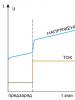
To unlock the full potential of the voltage converter, you need inductance, which I don’t have (see point 5 above), so the converter I assemble has obviously worse parameters. But my workload is quite small. When connecting a real load from a microcontroller and an OLED display, the following load table is obtained.
Great, let's move on.
Features of voltage measurement with a microcontroller
The ATtiny85 microcontroller has a 10-bit ADC. Therefore, the read level lies in the range 0-1023 (2^10). To convert to voltage, use the code:float Vcc = 5.0; int value = analogRead(4); / read the readings from A2 float volt = (value / 1023.0) * Vcc;
Those. It is assumed that the supply voltage is strictly 5V. If the microcontroller's supply voltage changes, the measured voltage will also change. Therefore, we need to know the exact value of the supply voltage!
Many AVR chips including the ATmega and ATtiny series provide a means of measuring internal reference voltage. By measuring the internal reference voltage, we can determine the value of Vcc. Here's how:
- Set analogReference(INTERNAL).
- Take ADC readings for the internal 1.1 V source.
- Calculate the Vcc value based on the 1.1 V measurement using the formula:
What follows:
Vcc = 1.1 V * 1023 / (ADC readings)
A function for measuring the controller supply voltage was found on the Internet:
readVcc() function
long readVcc() ( // Read 1.1V reference against AVcc // set the reference to Vcc and the measurement to the internal 1.1V reference #if defined(__AVR_ATmega32U4__) || defined(__AVR_ATmega1280__) || defined(__AVR_ATmega2560__) ADMUX = _BV (REFS0) | _BV(MUX3) | _BV(MUX1); #elif defined(__AVR_ATtiny44__) || defined(__AVR_ATtiny84__) (MUX0); #elif defined (__AVR_ATtiny45__) || defined(__AVR_ATtiny85__) ADMUX = _BV(MUX2); #else ADMUX = _BV(MUX3) | MUX2) | _BV(MUX1); #endif delay(75); // Wait for Vref to settle ADCSRA |= _BV(ADSC); // Start conversion while (bit_is_set(ADCSRA,ADSC)); ADCL; // must read ADCL first - it then locks ADCH uint8_t high = ADCH; // unlocks both long result = (high<<8) | low;
result = 1125300L / result; // Calculate Vcc (in mV); 1125300 = 1.1*1023*1000
return result; // Vcc in millivolts
}
For screen output, the Tiny4kOLED library with a 16x32 font included is used. To reduce the size of the library, 2 unused characters (, and -) were removed from the font and the missing letter “B” was drawn. The library code has been changed accordingly.
Also, to stabilize the output measurements, the function c was used, thanks to the author dimax, works good.
I debugged the code on a Digispark board in the Arduino IDE. After which the ATtiny85 was desoldered and soldered onto the breadboard. We assemble a breadboard, use a trimmer to set the voltage at the output of the converter (at first I set the output to 5V, while the current at the input of the converter was 170mA, I reduced the voltage to 4.5V, the current dropped to 100mA). When the ATtiny85 is soldered to the breadboard, the code has to be uploaded using a programmer, I have a regular USBash ISP. 
Program code
// SETUP /* * Set #define NASTROYKA 1 * Compile, upload the code, run, remember the value on the display, for example 5741 * We measure the real voltage at the output of the converter with a multimeter, for example 4979 (this is in mV) * Count (4979/5741)* 1.1=0.953997 * Calculate 0.953997*1023*1000 = 975939 * Write the result in line 100 in the form result = 975939L * Set #define NASTROYKA 0 * Compile, upload the code, run, done.
As mentioned above, the controllers have an internal 1.1V reference voltage. It is stable, but not accurate. Therefore, its actual voltage most likely differs from 1.1V. To find out how much it actually is, you need to calibrate:

* Set #define NASTROYKA 1
* Compile, upload the code, run it, remember the value on the display, for example 5741
* We measure the real voltage at the output of the converter with a multimeter, for example 4979 (this is in mV)
* We consider (4979/5741)*1.1=0.953997 - this is the real voltage of the reference voltage source
* We count 0.953997*1023*1000 = 975939
* We write the result in line 100 in the form result = 975939L;
* Set #define NASTROYKA 0
* Compile, upload the code, run, done.

Using the DipTrace program we lay out a board the size of an OLED display 37x12mm

Half an hour of unloved LUT activity.

Find 10 differences
The first time I screwed up and etched the mirror board, I only noticed it when I started soldering the elements. 
Solder it. SMD inductance 4.7 μH was kindly provided to me, thank you very much, Sergey.

We assemble a sandwich from a board and a screen. I soldered small magnets at the ends of the wires; the voltmeter itself snaps onto the battery being measured. Neodymium magnets lose their magnetic properties when heated above 80 degrees, so they need to be soldered with a low-melting Wood or Rose alloy very quickly. We perform calibration again and check the accuracy of the measurement:


I liked the review +126 +189
The goal of this case was to build a very accurate voltmeter, with 3 digits after the decimal point. I needed a constant voltage voltmeter showing voltage values in the range of 0-10 V. It was not suitable. Therefore, after deciding on independent implementation, the choice fell on the ICL7135 chip.
Precision digital voltmeter circuit
The generator is made on a 4047 chip, it must also power the negative voltage converter. The voltmeter has three measurement ranges: 2 V, 20 V, 200 V.

The divider uses 0.1% resistors. When starting the system, a calibration problem occurred. Without access to a reference device with an accuracy of at least 5 digits, it was decided to buy a ready-made source of stable voltages for calibration. It is based on the AD584KH and provides four levels: 2.5 V and 5.0 V, 7.5 V and 10.0 V.

The attached photographs show the measured values. The voltmeter case was made of sheet steel torn from an old computer case. The power supply comes from a 15 V DC power supply.

The accuracy is really super high. The readings are really stable, even on open (not shielded) measuring wires the last digit does not “jump”.