VAZ 2110 gearbox disassembly and assembly. Disassembling the gearbox and troubleshooting its parts. Roller bearings, what radial clearance is acceptable
Assemble the gearbox in the reverse order of disassembly. Please note the following:
– before attaching the rod joint and lever to the gear selector rod, degrease the threaded holes in the joint body and in the lever hub, as well as the fastening screws, apply special glue TV-1324 to the screw threads and tighten them.
The lever and hinge mounting screws have different lengths, coatings and tightening torques. The lever fastening screw is phosphated (dark color), 19.5 mm long, its tightening torque is 33.3 N m (3.4 kgf m), and the hinge fastening screw is cadmium plated (golden color), 24 mm long, its tightening torque 19.1 N·m (1.95 kgf·m).
– before installing the oil seals for the input shaft and gear selector rod, as well as the clutch release fork shaft, lubricate the working surface of the seals with a thin layer of Litol-24 grease and CV joint grease-4 on the clutch release fork shaft bushings;
– along the outer diameter, install the input shaft oil seal, drive oil seals and the gear selector rod oil seal housing on the liquid gasket KLT-75TM or TV-1215;
– after installing the gear selection rod into the clutch housing, check that the flange of the joint tip fits inside the groove of the boot along the entire perimeter;
– tighten fasteners to the torques specified in Appendix 1;
– assemble the secondary shaft in the reverse order of disassembly, while installing the synchronizers on the shaft in the assembled state using mandrel A. 70152, preheating them to a temperature of 100 °C and replacing the retaining rings of the synchronizer hubs with new ones.
When heated parts cool, the locking rings on the gear cones may jam. To eliminate this, before installing the heated synchronizer on the shaft, install a special fork-shaped gasket between the blocking rings and the ends of the gears, which is removed after the parts have cooled.
Installation of the synchronizer for 1st and 2nd gears and the driven gear of 2nd gear
When assembling the synchronizer, install the blocking rings so that the protrusions are located opposite the hub sockets for the clamp springs " A"of a smaller height, not a larger one, otherwise the gears will not change after assembly.
To make it easier to install the retainer on its ball, apply a little grease, place it in the cracker and, pressing the spring with a screwdriver towards its socket, install the cracker and ball assembly in place. In this case, a socket (of greatest depth) in the sliding coupling should be located opposite the ball.
Assemble the differential in the reverse order of disassembly, having previously lubricated the side gears and satellites with oil. The axial clearance of the axle gear should be no more than 0.4 mm, and the moment of resistance to rotation of the differential gears should not exceed 10.0 N·m (1.0 kgf·m). If the gap is increased, which is a sign of wear on the differential parts, replace the worn parts with new ones.
Using mandrel 67.7853.9565, press the inner rings of the bearings onto the differential box, having previously installed the speedometer drive drive gear.
Having installed the clutch housing on the stand for assembling the gearbox, press the rod oil seal into the socket using a mandrel 67.7853.9563, and then insert the gear selection rod into the hole in the housing and secure the gear selection lever to it, having previously degreased the threaded hole and screw and applied special glue to the screw threads TB-1324.
Using mandrel 67.7853.9574, press the outer rings of the roller bearings of the primary and secondary shafts assemblies with separators into the clutch housing sockets, and press the inner rings of these bearings onto the shafts. Press the outer rings of the differential bearings using the mandrel 67.7853.9575.
Install the gear selector, making sure that the selector rod lever is correctly positioned relative to the gear selector lever. Secure the gear selector.
Press the oil seal into the clutch housing to a depth of (4.2 ± 0.2) mm from the end of the housing so that the working edge of the oil seal is located on the polished belt of the shaft.
Install the differential into the crankcase. To prevent the semi-axial gears from moving from their seats during assembly, secure one of them on the clutch housing side with a technological mandrel or a plug used when transporting the gearbox.

Installing shift rods and forks
Install the input and output shafts and gears at the same time. Then install the axle with the reverse gear, making sure that the reverse fork fits into the groove of the intermediate gear. Then install the shift rods and secure the forks to the rods.
Install the cleaned magnet into the housing socket.
Install a gasket between the clutch housing and the gearbox housing, or instead of a gasket, apply liquid gasket KLT-75M or TV-1215 with a continuous roller with a diameter of 2 mm along the entire perimeter of the clutch housing and gearbox from the rear cover.
Select the differential bearing adjusting ring as indicated below (see subsection " Selection of differential bearing adjusting ring ").
Install the selected adjusting ring into the gearbox housing housing and press in the outer ring of the differential tapered roller bearing using mandrel 67.7853.9575.
Reinstall the speedometer drive.
Install the gearbox housing onto the clutch housing and secure it with nuts. Install adjusting rings into the bearing grooves of the primary and secondary shafts.
Install the thrust plate and, replacing the toothed washers with new ones, tighten the screws securing the plate.
Reinstall the rod clamps and reverse forks. Install the gaskets and tighten the plugs of the rod clamps and the reverse fork.
After installing the 5th gear parts on the primary and secondary shafts, screw on the nuts and tighten them with a torque wrench, then caulk the nuts. The length of the caulking should be 3.5–4 mm and should not extend onto the shaft thread. When tightening the nuts on the shafts, lock the input shaft using tool 41.7816.4070.
Page 1 of 4
It is more convenient to work together.
We screw the filler and drain plugs into place.
Remove the power unit support.
Remove the reverse light switch.
Remove the speedometer drive.
Remove the coupling with the bearing and the foam rings of the front cover.

Using a 12mm wrench, unscrew the three bolts securing the bearing cover (the bolts are installed on the sealant).

Remove the cover with gasket.

When installing it later, pay attention to the coincidence of the oil drainage channel in the cover and the hole in the crankcase.

Using a screwdriver, we remove the cuff of the input shaft from the cover (when disassembling the gearbox, we replace all cuffs regardless of their condition).

Using a mandrel or a head of suitable diameter, we press in a new cuff.

Using a 13mm wrench, unscrew and remove the bolt securing the reverse gear axis bushing to the front crankcase

Use a thin screwdriver to pry up and remove the retaining ring of the input shaft bearing

Using a 12 key, unscrew and remove the breather.

Using a 12mm wrench, unscrew the ten bolts connecting the front and rear crankcases (the two bolts passing through the mounting sleeves are longer than the others).

11. Carefully tapping with a hammer through the brass mandrel, uncouple the front and rear crankcases.
In this case, you must not strike the end of the input shaft, as the synchronizers will be damaged.

We disconnect the gearbox housings

Carefully, trying not to damage, remove the sealing gasket
We remove the adjusting shims from the bore under the intermediate shaft bearing in the front crankcase (they may not be there).
In this case, the axial clearance in the bearings is established only by the inter-crankcase sealing gasket.
Disassembly and assembly of the gearbox
Disassembly and assembly of the gearbox
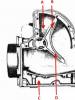
The red arrows indicate the nuts securing the clutch housing to the gearbox.
The white arrow indicates the hole in the front cover for releasing oil from the gearbox housing to prevent oiling of the clutch discs.

The arrow indicates the direction in which you need to move the lever to disengage it from the heads of the gear shift rods and remove the rear transmission cover.
1 – screw with an eye for fastening the tension spring of the gear shift lever;
2 – lever release spring;
3 – gear shift lever;
4 – screw for limiting the lateral travel of the lever.

1 – reverse fork;
2 – tension spring of the gear shift lever;
3 – guide cup of the lever;
4 – ball joint of the lever;
5 – gear shift lever;
6 – spherical washer;
7 – lever spring;
8 – retaining ring;
9 – damper locking sleeve;
10 – elastic damper bushings;
11 – damper spacer bushing;
12 – damper thrust pad;
13 – gear shift lever rod;
14 – shift fork for III and IV gears;
15 – shift fork for 1st and 2nd gears;
16 – fork rod for 1st and 2nd gears;
17 – fork rod for selecting III and IV gears;
18 – reverse fork rod;
19 – blocking crackers;
20 – clamp cover;
21 – bushing;
22 – clamp spring;
23 – retainer ball;
24 – rear cover of the gearbox;
25 – reverse light switch;
26 – remote bushing for the reverse fork rod.

1 – retaining ring;
2 – spring washer;
3 – bearing;
4 – input shaft;
5 – synchronizer spring;
7 – retaining ring;
8 – bearing.

1 – retaining ring;
2 – spring washer;
3 – synchronizer hub;
4 – synchronizer clutch;
5 – retaining ring;
6 – synchronizer blocking ring;
7 – synchronizer spring;
8 – washer;
9 – third gear gear;
10 – secondary shaft;
11 – 2nd gear gear;
12 – washer;
13 – synchronizer spring;
14 – blocking ring;
15 – retaining ring;
16 – synchronizer hub;
17 – synchronizer clutch;
18 – retaining ring;
19 – synchronizer blocking ring;
20 – synchronizer spring;
21 – washer;
22 – 1st gear gear;
23 – bushing of the 1st gear gear;
24 – bearing;
25 – reverse gears;
26 – spring washer;
27 – retaining ring;
28 – speedometer drive gear;
29 – rear bearing;
30 – oil seal;
31 – elastic coupling flange;
32 – nut;
33 – seal;
34 – centering ring;
35 – retaining ring.

1 – tension spring bolt;
2 – washer;
3 – tension spring;
4 – gasket;
5 – guide cup;
6 – gasket;
7 – washer;
8 – limit bolt;
9 – gear shift lever;
10 – ball joint;
11 – spherical washer;
12 – spring;
13 – support washer;
14 – retaining ring;
15 – gasket;
16 – flange;
17 – spring washer;
18 – nut;
19 – cuff;
20 – inner cover;
21 – lever rod;
22 – handle;
23 – thrust pad;
24 – elastic bushing;
25 – spacer sleeve;
26 – elastic bushing;
27 – locking sleeve.
Disassembling the gearbox
EXECUTION ORDER
1. Wash the gearbox and install it on a stand. Drain the oil and remove the bottom cover with gasket.
2. Remove the clutch release fork, and from the guide sleeve of the front cover of the gearbox, remove the clutch assembly with bearing and connecting spring.
3. Remove the clutch housing with the gasket and the front cover of the gearbox (along with the oil seal and spring washer) (see Fig. Internal view of the clutch housing).
4. Remove the speedometer drive with the gasket and the reverse light switch, being careful not to deform its housing.
5. Remove the bolt securing the shift fork for 3rd and 4th gears. Install clamp 41.7816.4068 on the input shaft or engage two gears at the same time. This will prevent the primary, secondary and intermediate shafts from turning and will allow subsequent disassembly operations to be performed.
6. Remove the snap ring from the end of the transmission output shaft.

7. Having straightened the lock washer, unscrew the nut a few turns to move the centering ring of the elastic coupling, and tighten the nut again. Using a pusher A.40006/1 with a puller A.40005/4, remove the centering ring of the elastic coupling of the cardan shaft from the end of the secondary shaft.

8. Remove the seal of the centering ring of the elastic coupling from the end of the secondary shaft, unscrew the nut and use puller 4 A.40005/3/9B/9 to remove the flange of the elastic coupling 1 (2 – bolts securing the device to the flange; 3 – strip 9C of puller A.40005/ 3).

9. Remove the rear cover of the gearbox by unscrewing the nuts securing it and screw 4 (see Fig. Internal view of the rear cover of the gearbox) limiting the lateral travel of the lever, and also moving the gear shift lever to the left to free it from the gear shift rods.
10. Remove the rear bearing from the output shaft. Remove the speedometer drive gear.
11. Remove the fork with the spacer bushing from the reverse control rod, and the reverse intermediate gear from the axle.
12. Remove the reverse drive gear retaining ring from the intermediate shaft, remove the gear and spring washer.

13. Remove the reverse driven gear retaining ring from the output shaft, pressing the spring washer with mandrel 41.7816.4069 to relieve the load on the retaining ring. Remove the reverse driven gear and spring washer.
14. Using shaped mandrels (such as screwdrivers) and rod drifts, remove the front and rear intermediate shaft bearings from the gearbox housing. Make marks on the inner rings of the double-row front bearing, according to which these rings should be installed in their original places in the outer ring of the bearing.
15. Remove the intermediate shaft from the gearbox housing by tilting it as shown in the figure.

16. Remove cover 20 (see Fig. Gear shift drive) of the rod clamps along with the gasket, remove the springs and clamp balls. Remove rod 18 for reverse gear and rod 17 for shift fork for 3rd and 4th gears from the gearbox housing. Unscrew the bolt securing the forks of 1st and 2nd gears, remove the rod and forks. When removing the rods, simultaneously remove three locking blocks 19.
17. Unscrew the screws securing the locking plate of the secondary shaft intermediate bearing with a drill screwdriver and remove the locking plate of the secondary shaft intermediate bearing and the axis of the reverse intermediate gear (the arrow indicates the direction of the impact stroke of the screwdriver cage when struck with a hammer).

18. Using mandrels (such as screwdrivers), remove the input shaft along with the bearing and synchronizer ring and remove the needle bearing from the front end of the secondary shaft.

19. Knock the secondary shaft out of the intermediate bearing, remove the intermediate bearing and, tilting it as shown in the figure, remove the secondary shaft assembly with gears, clutches and synchronizer rings from the crankcase. Remove the synchronizer clutch for 3rd and 4th gears from the shaft.

Disassembling the gearbox input shaft
20. Remove the retaining ring 7 (see Fig. Parts of the input shaft), the blocking ring 6 and the synchronizer spring 5.
21. Place the shaft on the press and, using a mandrel 41.7816.4069, compress the spring washer 2, remove the locking ring 1, then the spring washer and bearing 3.
Dismantling the secondary shaft of the gearbox
22. Remove gear 22 from the rear side of the shaft (see Fig. Details of the secondary shaft) of the 1st gear with sleeve 23, hub 16 with a sliding clutch for switching 1st and 2nd gears, gear 11 of the 2nd gear together with the synchronizer blocking ring 14.
23. Install the secondary shaft with a mandrel 41.7816.4069 on a press, place support half rings 3 under the 3rd gear gear, and, pressing the mandrel on the spring washer, remove the locking ring 2, then the spring washer 4, the hub of the sliding clutch for shifting 3rd and 4th gears and the gear III gear.

Disassembling the gear shift lever and rear cover
24. Remove the cuff 19 (see Fig. Parts of the gear shift lever), the lever cover 20, then the lock ring 14, washer 13, spring 12 and spherical washer 11.
25. Unscrew the nuts securing the flange 16, disconnect the tension spring 3 of the lever from the eye of the bolt 1 and remove the lever together with the flange, support 10 and cup 5.

1 – spring washer;
2 – mandrel 41.7816.4069;
3 – locking ring;
4 – reverse gear of the secondary shaft.
Gearbox Assembly
EXECUTION ORDER
The gearbox is assembled in the reverse order of disassembly. Please note that:
– spring 22 (see Fig. Gear shift drive) of the reverse fork rod retainer ball differs from others in elasticity, it is painted green or has a cadmium coating;
– when installing the clutch housing with the front cover of the gearbox, the hole in the front cover should be located as shown in Fig. Internal view of the clutch housing;
– before installation, coat the working surface of the oil seals with LITOL-24 lubricant;
– when installing the reverse gear retaining ring, use mandrel 41.7816.4069, and when installing bearings and shaft seals, use mandrels 41.7853.4028, 41.7853.4032, 41.7853.4039.
Disassembling and assembling a gearbox on a VAZ 2110 car is a fairly simple procedure if you follow all the necessary steps step by step.
Before you begin directly disassembling the box of your car, you need to find out whether it has previously undergone any repairs. If some parts have already been replaced, be it bearings or, for example, the clutch drive housing, before disassembly you will have to replace the adjusting ring located on the differential bearing. This manipulation will have to be done before work begins.
Plan for dismantling the gearbox step by step
- First of all, after dismantling the faulty gearbox from the car, it will first have to be cleaned of traces of dirt and grease formed during operation, for which it should be washed from the outside.

- First of all, the pointer that serves as an oil level indicator is removed.

For convenience, it is better to place the box in a vertical position.
- The next step is to remove the special clutch cable bracket. This can be done by unscrewing one bolt with a flat-shaped washer installed on it and a pair of nuts with a spring-type washer.
- Then you should remove the cover located on the back of the box. It is secured with six bolts that can be unscrewed without much effort.

- The lid can be completely removed by slightly lifting the tide located on it. The easiest way to do this is with a flat screwdriver.
- To release the fifth gear fork, tighten one bolt with a spring washer.
- To continue disassembling the box, it is necessary to carefully fix all the shafts to avoid their accidental rotation. This can be done by shifting to fifth gear and moving the fork and synchronizer clutch down. As soon as the gear connects to the coupling splines, you need to shift down one or two gears. This can be done by moving the gear selector rod.
- The next step is to unscrew the nut securing the input shaft. Since it usually twists quite tightly, you will have to put in a lot of effort.
- Carry out similar manipulations with the secondary shaft.
- Using several screwdrivers, you should slightly lift the so-called driven gear located in 5th gear. During this manipulation, the hub located on the synchronizer is removed with force from the shaft. The gear must be removed not just one, but together with the synchronizer and fork. This step will have to be done with caution - if the clutch moves from the synchronizer and remains on the hub, there is a risk of destruction of the balls that secure it.
At the next stage, the plug must be removed from the synchronizer. This must be done through the groove located in the coupling, having previously dismantled the thrust plate.
In addition to the plate, it is also necessary to remove the locking ring and the 5th gear. Since the teeth of the moving ring and coupling have become worn in during operation, during further assembly these elements of the box must be installed in the same position as before disassembly. To do this, it is better to number these elements before disassembling. Quite often, when disassembling the box, there is no need to completely disassemble the synchronizer itself; in this case, it can be carefully bandaged.- The next step is to remove the bushing from the secondary shaft.
- Then remove the fifth gear drive gear from the primary shaft, having previously remembered its original position.15. For the next manipulation of the bearing plate, you will need an impact screwdriver. It is secured using four conventional bolts and spring washers. By unscrewing the fastening, it can be removed. Then you can remove the thrust washer from the secondary shaft.

15. Then it is necessary to remove the fixing bearing rings from the two shafts, carefully holding them and slightly lifting them with your hand.
16. After this, you can unscrew the special clamps to remove the balls and springs.
17.The next step is to unscrew the special clamp designed for reverse gear, remove the O-ring and remove the spring.
18. After this, you can pull the ball out of the retainer, for which you just need to lift the box a little.
19. At the next stage, it is necessary to unscrew all twelve nuts located on the crankcase mounting and one bolt with spring-type washers.
Importantremember the relative positions of the parts. The technological plug must also be removed. We continue work in the following order:
- The clutch housing should be dismantled by inserting a regular screwdriver into one of the three grooves located along it.
- The gearbox housing can be quite easily removed from the clutch housing if you turn it a little while simultaneously lifting it slightly up and to the left until it completely comes out from under the gear.
- Fastening the forks to engage the first four gears must be unscrewed.
- The next step is to slightly raise the rod that shifts the first two gears. After the rod completely comes out from under the support, move it to the left side until the head begins to cling to the bracket. Then you need to remove the rod fork from a special groove located on the synchronizer coupling. After the rod and fork are removed, the fork can also be removed. But, if there is no particular need for this, it is better to leave the fork as is.
- The head can be removed from the rod designed for shifting third and fourth gears. To do this, you just need to turn it, thereby disconnecting the head from the gear lever. The rod should be deprived of support, which is quite simple to do if you lift it slightly and then remove it from the forks, having first taken them out of the groove on the coupling.
- It is not at all difficult to remove the shift rod for the last 5th gear from the support; you just need to turn it a little and remove the head that is connected to the locking bracket.
- The next stage of disassembly is the removal of the axis on which the intermediate gears intended for engaging reverse gear are located.
- You should move the gear until it stops with the mechanism designed for selecting gears and, turning it about 30-40 degrees, remove the intermediate gear from the gears located on the shaft.
- Then you should swing the shafts and carefully remove them.
- The next step is to dismantle the differential itself in the clutch housing.
- After this, it is necessary to unscrew the mount in the mechanism intended for selecting gears. To do this, unscrew the three bolts with spring-type washers, then the mechanism itself can be easily removed.
- Remove the magnet located in it from the clutch housing.
- The next step is to unscrew the nut on the speedometer housing, and then remove the housing itself. At this stage, you should pay maximum attention to the condition of the elastic ring - if it is not elastic enough or is damaged, it will have to be replaced.
- The crankcase also contains a light switch for reverse gear, which also needs to be unscrewed. There is a metal sealing ring underneath it.
- The next step will require a puller to press the bearing out of the output shaft. In extreme cases, you can get by with a regular flat-head screwdriver.

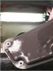
16. Then remove the oil pan located under the bearing.
17. Similar manipulations must be carried out with the bearing and on the input shaft.
18. When assembling, new bearings purchased in a store must be driven all the way into the clutch housing; you can use the most suitable mandrel in size.
19. Using a regular screwdriver, move the edge located at the rod in the protective case and intended for selecting gears. It moves simultaneously with the support sleeve.
20. Remove the rod intended for selecting the gear, you can unscrew the bolt from the fastening of the lever itself, after which you can remove the lever itself.
21. If you need to change the hinge of the rod, you will have to move the special protective cover, and then unscrew the bolt from the hinge mount. Disassembly at this point needs to be done quite carefully, since for greater strength, a special TB1324 glue was applied to the bolt, which also needs to be applied during assembly. If the rod has been damaged or lost its properties during operation, it is better to replace it immediately.
After completing the above steps, you can replace the necessary components in the gearbox. Assembly is carried out in the reverse order of disassembly.
Good luck with your transmission repair!
I bring to your attention an article on repairing a new 5-speed gearbox (the so-called “broken package”)
Some of the photos of the process will be repeated, please don’t push too hard, the photos were mainly taken during assembly, since the gearbox and parts were washed, and the camera remained clean :).
What additional tool will be required? A retainer for the input shaft (I made it from an old clutch disc hub), a high 30" socket for loosening the output shaft nut, a pair of powerful screwdrivers, a circlip remover, an impact screwdriver with a hammer and, ideally, a torque wrench.

It’s unlikely that anyone will have a special stand at hand for repairing a gearbox; in principle, you can sort it out on a table, or you can also carefully clamp it in a vice.
So, we drain the oil from the gearbox, remove the gearbox from the car, remove the elastic coupling, the rear gearbox mount along with the yoke and remove the clutch fork with boot and release plate.
We thoroughly clean the gearbox from dirt using a metal brush, a suitable tool such as a screwdriver, and ideally blow it out with a compressor.
Even though the oil has been drained, there is still some oil left in the gearbox, so we take this fact into account when disassembling.
Remove the lower gearbox cover.


We remove the rubber boot of the coupling from the secondary shaft, the stopper from the secondary shaft, using a suitable drift, knock out the centering sleeve of the coupling. If you cannot “pick up” the sleeve, then unscrew the secondary shaft nut as much as possible and screw it back.
At the same time, the bushing will almost come off its place. We turn on any gear, fix the input shaft, and unscrew the secondary shaft nut to “30”. Remove the conical spring washer.


If you don’t have a primary shaft lock at hand, you can use an aluminum spoon by inserting its handle between the gears of the primary and intermediate shafts. Don't be afraid for the gears, the luminaire won't harm them.
Remove the flexible coupling flange.

Turn off the reverse light switch. Be careful not to lose the copper sealing washer.


We engage second gear and remove the gear shift lever housing by unscrewing the three nuts along the outer radius.

Unscrew the two nuts securing the trouser bracket to the gearbox

We remove the bracket and take out the mounting bolt with a square head located under it.

Unscrew the five nuts securing the rear cover on the outside and one on the inside.


We remove the back cover, sometimes you have to hit it lightly with a hammer. The bearings may become separated,
part of the bearing remains on the shaft, part in the back cover, no problem.

Remove the inner bearing ring (hereinafter referred to as P.) from the secondary shaft, then remove the speedometer drive gear.
AHTUNG! There is a small ball under the drive gear, don't lose it!


We remove the oil deflector washer. We inspect it; there was a case when the washer came off the bushing.

Using a screwdriver, set the 1-2 gear shift rod to the neutral position.
We fix the input shaft and remove the bolt securing the gear block with a “17” head. Then it will go by hand,
but we don’t turn it away yet.

Now you need to remove the clutch cover (aka bell). We unscrew one nut to “13” and six nuts to “17”.

We remove it and put it aside. A spring cone washer remains on the input shaft or in the bell.
We inspect it for wear and cracks. Sometimes, instead of a cone washer, there may be a thick ring.

Holding the input shaft with the clamp, unscrew the front bolt of the intermediate shaft (hereinafter referred to as the washout) with a head set to “19”.

We unscrew the two bolts of the plate that holds the springs of the gear shift rod clamps.

Under the plate there are three springs, two of the same length (for the 1-2 and 3-4 gear rods) and one longer (for the 5th gear and reverse rod).
We take out the springs.


There are three balls under the springs, they are in oil and do not fall out on their own, but still keep an eye on them
during further disassembly.

Now unscrew the gear block bolt and remove it. Now we take out the gear block. Move backwards and sideways.
The 5th gear gears move back a little.


A spacer ring is installed between the gear block and the rear shaft shaft. It sometimes sticks to the gear block
and at the most inopportune moment it disappears.


We remove the 5th gear assembly from the secondary shaft with the 5th gear shift rod, the Z.H. gear, and the clutch.

Remove the spacer ring.

Using a suitable thin object, push the retainer ball out of the socket. I use a tube from VD 40, it is flexible.
Now, using pliers, we open the retaining ring of the 5th gear synchronizer clutch hub and remove it.


Remove the hub from the secondary shaft of the gearbox.

Remove the spring washer. It faces the Z.H. gear.

Removing the reverse gear

Now you need to remove the wash shaft. To do this, you need to remove the front bearing.
Sometimes it is enough to catch the locking ring with screwdrivers and the P. will come out.

Sometimes it doesn’t want to come off, then you have to tighten the bolt a few turns into the hole and, creating a stop with a screwdriver, slightly
tap the bolt with a hammer and move the bearing out of place. Sometimes the bearing is disassembled, no problem, it can be reassembled.

Now we remove the rear P. shaft by pushing it out of the housing with a screwdriver.

We take out the sump.

We unscrew the bolt securing the 3-4 gear fork to the 3-4 gear shift rod with the head set to “10”.


AHTUNG! There is a small locking block located in the shift rod. When the rod is pulled out, it may fall out.


We take out the locking ball.
We unscrew the bolt securing the 1-2 gear fork to the 1-2 gear shift rod with the head set to “10”.

We take out the rod and at the same time pull out the plug.


Then remove the locking block from the gearbox housing.
We take out the locking ball.
We take out the input shaft.

We remove the needle bearing. We inspect the friction surfaces of the needle bearing inside the input shaft and on the secondary shaft.
If there are traces of chipping, the shaft will have to be replaced.

We wash the bearing and carefully inspect it; the treadmill and balls should not have any signs of chipping or pitting
An oiled bearing should rotate quietly, without jamming or noise.
This is what a worn out treadmill looks like - the cause of the noise

If there is a need to replace the bearing, then:
Remove the retaining ring from the outer race of the bearing

Using a puller, remove the retaining ring; if it doesn’t come off, then knock it off with a drift,
remove the spring washer


We press out the bearing and press on a new one. We press the retaining ring into place using a bit
blow along the shaft

Using an impact screwdriver and a hammer, pry it out of place and unscrew the three screws of the locking plate.


If there is no damage, the screws can be reused, but we always install new castle washers during assembly.
Remove the locking plate.

We remove the bearing from the gearbox housing complete with a lock washer.

Holding the gears on the shaft, pull out the secondary shaft assembly from the gearbox housing.


We wash the body.

This is what the removed secondary shaft assembly looks like.

We remove the 3-4th gear clutch from the shaft and inspect the clutch. There should be no nicks on the teeth.
Now we disassemble the secondary shaft to inspect 1st and 2nd gears. All parts are simply removed from the shaft.
Sometimes the hub of 1-2 gears can fit quite tightly, a couple of light blows to the 2nd gear gear and the hub will come off.
This is what the 1st and 2nd gear parts removed from the secondary shaft look like.


If you need to gain access to the 3rd gear and the locking ring, then disassemble the shaft in the following order:
We clamp the shaft in a vice through a rag.

It is not possible to release the stopper; we knock it out of place with a drift and the ring will pop out on its own.


Remove the spring washer.

Remove the clutch hub.

Remove the 3rd gear gear assembly.

We replace worn parts.
We put the gear, hub, and spring ring in place.


Using a circlip remover, place the circlip as close as possible to its location on the shaft.
Using a punch, strike from above and along the perimeter of the ring to push the retaining ring into place.

We inspect the gears, the teeth should not have nicks, the edges should be sharp

We inspect the gears; chipped teeth are not allowed.
When purchasing a new gear, pay attention to the teeth of the gear itself - there should be no nicks or other defects.
There were new gears with nicks, which caused noise.
We inspect the synchronizer blocking ring; there should be no marks on it from the coupling (notches along the ring or a ring-shaped groove)
In the photo on the left is a worn ring, on the right is a new one.


To replace the blocking ring, press the ring against the gear (compressing the spring)
and use a puller to open the retaining ring

Remove the stopper and locking ring

We put a new ring, put it back together, check the ease of movement, it shouldn’t stick.
We inspect the coupling-nicks on the teeth; there should be no signs of wear in the groove for the fork
Worn clutch

New clutch

We inspect the shift forks. Wear on the working surface of the fork is not allowed.
For comparison - new and worn fork


We change the input shaft oil seal.
From the clutch side, through the hole in the release bearing guide sleeve, use a drift of suitable diameter
knock out the seal.

Thoroughly clean, degrease, lubricate with a thin layer of sealant,
We put the oil seal in place using a socket on “32”.

We examine the supporting “soldier” of the clutch fork for wear.
We inspect the spring thrust washer (wear of the supporting surfaces, cracks are not allowed).
We apply a little lithol to the seat of the washer and put it in place. With the help of lithol, the washer is “glued” and will not fall out during assembly.

Let's now work on the back cover.
As a rule, the race of one or two bearings remains in it. And the oil seal also needs to be changed.
We knock out the plug using an extension cord.

We knock out the oil seal using a screwdriver.

Using a screwdriver and a hammer, knock out the bearings from the rear cover housing.P. They sit without tension, so they come out easily.

We wash the body, degrease the oil seal seats and plugs.
We apply sealant to the seats of the oil seal and plug.
Press in the oil seal and plug.