LDS power supply from 12 volts to ne555. How to power an LDS from a car battery. Fluorescent lamp, battery powered and dimmable
This circuit was taken from Radiohobby magazine No. 3 for 1999 and is a step-up voltage converter built on the principle of a blocking oscillator. Generation is carried out due to positive feedback that controls the operation of the key transistor. In this case, short-term high-voltage pulses are generated on the secondary winding of the transformer. When the converter is turned on, the fluorescent lamp has a high resistance, the voltage on its electrodes increases to 500 volts, but as soon as the lamp warms up, the voltage drops to 50 - 70 volts. Therefore, it is extremely important not to turn on the converter without a load, since the voltage on it can rise to 1000 volts, which can damage the transformer.

The figure shows two circuits, the top one is for a p-n-p structure transistor, the bottom one is for an n-p-n transistor. Naturally, when the structure of the transistor changes, the polarity of capacitor C1 also changes.
The transformer is manufactured on W-shaped ferrite 7x7 with magnetic permeability NM2000. The secondary winding is wound first, according to the diagram it is connected to the LDS. It contains 240 turns wound with PEV-0.23 wire. After which the winding is well insulated and the collector winding is wound on top of it - this is 22 turns wound with PEV-0.56 wire and the base winding, which contains 6 turns wound with PEV-0.23 wire. Naturally, the diameters of the wires can vary within small limits. The core required for the transformer being manufactured can be obtained from an old rotary telephone, for example TA-68. Then you must first remove all the old windings from its frame. Also, an W-shaped core of a suitable cross-section of the magnetic circuit can be taken from a computer power supply. Important! A gap is required between the halves of the W-shaped core - a gasket made of non-magnetic material. A sheet of thin paper, one layer of electrical tape, etc. will do. This is necessary so that the core does not become magnetized, otherwise the converter will stop working after a short time.
For the circuit to operate correctly, it is necessary to adjust the current consumed by the converter. To do this, you need to know the power of the LDS used. Let's say its power is 20 watts. Then the current consumed by the converter should be 20W/12V=1.66A. This current is set by selecting the base resistor R1.
Transistor T1 must be placed on the radiator. The area of the radiator is selected in such a way that after an hour of work you can safely hold on to it. Instead of transistors KT837F and KT805BM, you can use KT818 and KT819, respectively.
The functionality of the converter is checked as follows. If immediately after turning on the converter the lamp lights up dimly, and after a split second flares up at full strength, then everything is working normally. If the lamp continues to work dimly, then it is necessary to select R1, or even change the transistor. The wires from the transformer to the lamp must be as thick and short as possible, otherwise the lamp will light poorly or not light at all.
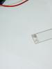
And now some photos.


Here is another design using the 555 microcircuit. The device is a DC-AC voltage converter, which is designed to power energy-saving lamps from a reduced voltage. Input voltage range 8-18 Volts (optimal 12 Volts). At the output of the transformer, a high-frequency alternating voltage of about 400 Volts is generated. This is a simple and stable single-ended voltage converter that can be used in camping situations or in the car.
Despite its compact size and simple design, the converter develops quite high power, which directly depends on the specific type of key used. Using a powerful field-effect transistor of the IRF3205 series, the power reaches 70 Watts. In my case, I used the IRFZ48 transistor, with a power of no more than 50 watts. It is not recommended to increase the power to more than 70 watts, since you will need to calculate the parameters of the pulse transformer again.

The 555 timer operates as a square wave generator. The pulses are amplified by a powerful field key. The transistor must be installed on the heat sink. The pulse transformer consists of only two windings. The primary winding consists of 7 turns. For ease of winding, 3 wire strands with a diameter of 0.5 mm each were used. This solution saves space. Then the boost winding is wound on top of the primary winding. This winding consists of 80 turns of wire with a diameter of 0.2 mm. The winding can be wound in bulk without additional insulating layers.

The core was used from an old ATX power supply. First, you need to remove the transformer from the block board and disassemble it. The ferrite halves are tightly glued to each other, so they need to be warmed up a little. You need to heat it carefully (with a lighter or a powerful soldering iron).

Afterwards, you need to remove all the windings and wind the necessary ones. Such a single-ended converter can power fairly powerful neon tubes up to 50 watts. The converter can also be used to power other electrical devices, including those designed for constant voltage, only in this case a rectifier is needed at the output.
The transformer is assembled on a W8x8 ferrite core. When making a transformer, pay attention to the quality of the winding. The winding should be winding turn to turn, with each layer wrapped with either capacitor paper or fluoroplastic tape. After winding all the windings, the transformer must be impregnated with epoxy resin diluted in alcohol to prevent breakdown of the windings.
I -30 turns PEV-2 0.3mm
II -12 turns PEV-2 0.3mm
III-550 turns PEV-2 0.3 mm
The dots indicate the beginning of the windings. First we wind the third winding, then we attach the terminal of the second winding to the terminal of the third winding and wind it in the opposite direction. Then, we wind the first winding.
The transistor must be placed on the radiator. The button serves to ignite the lamp if this does not happen immediately, but usually the lamps light themselves.
Connect the lamp, and then apply power (Not vice versa! Otherwise, the transformer may break through!). If the lamp does not light up, then swap the terminals of winding I.
List of radioelements
| Designation | Type | Denomination | Quantity | Note | Shop | My notepad |
|---|---|---|---|---|---|---|
| VT1 | Bipolar transistor | KT863A | 1 | To notepad | ||
| C1 | 100 µF | 1 | To notepad | |||
| C2(C1) | Electrolytic capacitor | 10 µF | 1 | To notepad | ||
| C3, C4 | Capacitor | 0.01 µF 1000 V | 2 | To notepad | ||
| R1 | Resistor | 1 kOhm | 1 | To notepad | ||
| R2 | Resistor | 470 Ohm | 1 | To notepad | ||
| Tr1 | Transformer | 1 | To notepad | |||
| LV1 | Lamp | 1 | To notepad | |||
| SW1 | Button | 1 |
Power supply for fluorescent lamps (LDS) from a 12 volt battery.
The converter allows you to power an LDS with a power of up to 20 W from a car battery with a glow duration of about 60 hours. The current consumption of the device is approximately 0.75 amperes. The schematic diagram of the converter is shown in the figure below.
Transformer TP1 is implemented on a ferrite Ш-shaped core Ш8х8. The wire is wound turn by turn, with each layer of wire wrapped in capacitor paper (thin fluoroplastic tape will do instead of paper). Pay special attention to the quality of winding of the transformer, wind it carefully, and at the end of the procedure, to avoid breakdown, impregnate it with epoxy resin (the resin is diluted with alcohol before impregnation).
Winding data of transformer TP1:
● I winding - 30 turns of PEV-2 wire with a diameter of 0.5 mm;
● II winding - 12 turns of PEV-2 wire with a diameter of 0.3 mm;
● III winding - 500 turns of PEV-2 wire with a diameter of 0.15 mm.
In the diagram, the dots indicate the beginning of each of the windings. Pay attention to the winding sequence:
● the third winding is wound first and wrapped with capacitor paper;
● the wire for the second winding is connected to the beginning of the first winding and it is wound in the opposite direction, then a layer of paper or fluoroplastic tape;
● the third winding is wound and then impregnated.
To avoid thermal breakdown of the transistor, it should be installed on a radiator, which can be made independently from sheet aluminum. The area of the radiator plate must be at least 20 cm2. For the parameters of the KT863 transistor, see the figure below.
Button SW1, which closes the circuit of capacitor C4, is necessary to start the LDS, but, as a rule, after power is applied to the converter, the LDS lights up immediately.
After assembling the converter, before turning it on, make sure again that there are no installation errors, connect the lamp and apply voltage to the device. The lamp should light up. If the lamp does not light up and the SW1 button does not help, check the serviceability of the transistor, if the transistor is working properly, swap the leads of the first winding, the generator should work.
Homemade neon lighting for the underbody of a car.
Fans of all kinds of “mulek”, “fenech”, and other automotive gadgets, along with the embellishment of the interior of their car, also get to the bottom of the body; they like it when, driving through the evening city, their bolivar glows like a New Year tree.
Of course, nowadays in stores you can buy all kinds of ready-made automotive gadgets, including underbody lighting, but sometimes not everyone is happy with the price. That’s why craftsmen have to put their hands to it to make such a “luminary” with their own hands.
Below we present to your attention a simple, repeated converter circuit capable of lighting fluorescent lamps with a power of 20 to 40 watts when powering the device from a 12-volt car battery.

It is worth noting that the purpose of this converter for LDS lamps is not limited to illuminating the underbody. It can be used as a backup lighting device when the main power supply is turned off (emergency lighting), or a portable low-voltage lamp can be made for use in all kinds of hikes (trips to the forest or fishing, outdoor recreation with an overnight stay, etc.). In general, the thing is useful, all that remains is to sculpt it, since the design of the device is quite primitive and parts for it are not in short supply. The only thing you need to pay attention to is the quality of the winding of the transformer, which, unlike the previous version described above, is wound on a ferrite rod with a diameter of 8 mm and a length of about 5 - 8 cm.
And this is how to wind a transformer:
● We take a ferrite rod of the size we need, wrap a layer of thin, well-sticking (preferably imported) electrical tape around it;
● We wind the high-voltage winding III as follows: we take a coil of wire with a diameter of 0.2 - 0.3 mm and solder a piece of multicore to the end, which will serve as a tap, apply ferrite to one edge of the ferrite wrapped in a layer of electrical tape, and wind tightly turn to turn one layer of winding until filling the ferrite length. We apply one layer of electrical tape to this layer of winding. We continue to wind in the opposite direction along the entire length of the ferrite rod. We also cover the second layer of the winding with a layer of electrical tape. In this way we wind the entire high-voltage winding. For lamps from 8 to 16 watts, the winding contains 600...700 turns, for lamps from 20 to 40 watts - wind 100 turns more.
![]()
● It remains to wind the primary and secondary windings. They are wound alternately in one direction as shown in the diagram (the dots indicate the beginning of the windings), and do not forget to lay a layer of insulating tape between these windings. The permissible wire diameter for winding the primary and secondary windings is 0.5...1.2 mm (it is better to choose something in between). The primary winding contains 25 turns, the secondary winding contains 45 turns.
![]()
During the process of assembling the device, do not confuse which winding is which, this may result in the fact that your LDS will not burn (at best), or the converter transistor will “crack” (at worst).
What else can you say about the assembly...
Diode KD226 can be replaced with any other “current” (3 amperes) diode, with a voltage of at least 50 volts, or some imported one with similar parameters (for example FR607 - current 6A, 1000 volts). Below for reference, see the characteristics of KD226 and select the appropriate one if you do not have what is indicated in the diagram.
Resistors R1 and R2 It’s better to install not half-watt ones, as in the diagram, but one-watt ones, especially R2, because during operation they tend to heat up. By selecting these resistors, the required current consumption of the converter is set (0.6...0.8A), which determines how brightly the lamp will glow. There is no point in increasing the current consumption; the difference in brightness with a further increase in current will not be large, and the transistor will glow “Mother, don’t worry...”. If, when setting up, the current is already quite high, but the LDS still does not want to shine normally, it is better not to chase the consumption current, but try to increase or decrease the capacitance of capacitor C1, its capacitance can be adjusted within 0.05...0.5 µF.
Resistance R1 is selected depending on the power of the lamp that you plan to use; its nominal value can lie in the range of 430 Ohm ... 2 kOhm. For example, when using an 8-watt LDS, R1 will be about 2 kOhm, and when using a 30…40W LDS, it will be within 360…820 Ohms.
Transistor KT805AM installed on a radiator, possibly made of sheet aluminum, with a cooling area of about 100 cm2. It’s better to put the finished device into operation for an hour, and then check how hot the transistor is. Slightly warm - that means it’s normal, it will live. Yes, and the quality of the lamp’s glow depends on the transistor; with one LDS it may not light up reliably, but with the same one it lights up immediately, although both transistors are working. The table below shows the parameters of KT805 transistors. Can be replaced with KT819G.
How to check the functionality of the converter:
● Be sure to connect the lamp (do not supply power to the inverter without the lamp connected, and do not disconnect the lamp while the inverter is running);
● Apply power to the inverter. The LDS lights up dimly at first, but after a second it lights up brightly - everything means good.
● If your light lights up dimly, and there is a glow along one edge of the LDS, try increasing Ipot; if the current consumption is normal, change VT1 to another.
● Do not make the wires connecting the lamp to the converter too long, and do not use too thin a wire for these purposes; this determines how well the LDS will ignite, and whether it will ignite at all.
● And one more way to check the converter: carefully move the wires from the high-voltage winding to a gap of approximately 5 ... 10 mm. If a trailing spark jumps in this gap, then the device is working. If not, shorten the wires, the number of turns of the high-voltage winding is not enough, or change VT1.

Attention!!! Be careful when setting up the converter, there is a high voltage on the 3rd winding of the transformer when power is applied to the circuit; Observe electrical safety precautions.
Lamps for illuminating the underbody.
In general, such lamps are produced not only with a white glow, they also come in pink, blue, and green. T4 standard lamps with a power of 20 watts are quite enough for these purposes. For example, you can use F20W T4 BLUE, this lamp has a blue glow. Dimensions of this lamp: length – 57cm, diameter – 1cm.
Before attaching the lamp to the underbody, wires are connected to its contacts and it is placed in a transparent PVC tube. The length of the tube is chosen to be 8...10 centimeters longer than the lamp, so that it is possible to fill the ends of the tube with liquid nails, and use self-tapping screws to attach the lamp to the body or frame using the remaining free areas.

PS. It is better to select the part ratings (R1, R2, C1) for each specific lamp. If the converter is configured at home when operating from a power supply, ensure that the LDS is reliably ignited at a voltage of 11 volts. When set to Up = 13V, and then installing the device on the car, the lamps may glow poorly even when using wires with a cross-section of 0.75 mm.


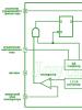
Presented to your attention voltage converter circuit (electronic ballast) to power a fluorescent lamp (LDS) from an autonomous 12 V source. The circuit is based on square wave generator, collected on a timer NE 555 .
Pulses from the generator output are supplied to the key transistor VT 1 and step-up transformer. As a step-up transformer, a ready-made network 220/12 can be used, connected in reverse (in the circuit, as you can see, 120V/6V is recommended).
Still, it is advisable to make the transformer yourself, this will increase the efficiency of the converter, as well as use a lamp with a power of up to 18W. The transformer is wound on an armored magnetic core made of 2000NM1 ferrite with an outer diameter of 30 mm. Winding I contains 35 turns of PEV-2 wire with a diameter of 0.45 mm, winding II ≈ 1000 turns of PEV-2 0.16. The windings must be insulated from each other by several layers of varnished fabric. To increase reliability, winding II must be divided into several layers, laying varnished cloth between them. The magnetic circuit cups are assembled with a gap of 0.2 mm and tightened with a screw and nut made of non-magnetic material. A transformer made on a magnetic core fromTV line transformer .
Resistor R 1, it is better to install a trimmer, this will help adjust the maximum brightness of the glow (when adjusted to the resonance frequency of the secondary winding, the current consumption will be significantly reduced).
When using a homemade transformer, capacitors C3, C4 can be eliminated.
Rice.1 Voltage converter for fluorescent lamp