Transistor voltage regulator 220 volts. Thyristor voltage regulator is a simple circuit, operating principle. Using the regulator in everyday life and safety precautions
Noise-free voltage regulator 220/0-220 volts 60 watts
Most voltage (power) regulators are made using thyristors according to a phase-pulse control circuit. It is known that such devices create a noticeable level of radio interference. The regulator proposed by the author of the article is free from this drawback.
A feature of the proposed regulator (see diagram) is the control of the amplitude of the alternating voltage, in which the shape of the output signal is not distorted, unlike phase-pulse control. The regulating element is a powerful transistor VT1 in the diagonal of the diode bridge VD1-VD4, connected in series with the load. The main disadvantage of the device is its low efficiency.
When the transistor is closed, no current passes through the rectifier and the load. If control voltage is applied to the base of the transistor, it opens and current begins to flow through its collector-emitter section, diode bridge and load. The voltage at the regulator output (at the load) increases. When the transistor is open and in saturation mode, almost all the mains (input) voltage is applied to the load.

The control signal is generated by a low-power power supply assembled on transformer T1, rectifier VD5 and smoothing capacitor C1. The variable resistor R1 regulates the base current of the transistor, and therefore the amplitude of the output voltage. When the variable resistor slider is moved to the upper position in the diagram, the output voltage decreases, and to the lower position, it increases. Resistor R2 limits the maximum value of the control current.
Diode VD6 protects the control unit in the event of breakdown of the collector junction of the transistor.
The voltage regulator is mounted on a board made of foil fiberglass 2.5 mm thick. Transistor VT1 should be installed on a heat sink with an area of at least 200 cm2. If necessary, diodes VD1-VD4 are replaced with more powerful ones, for example D245A, and are also placed on the heat sink.
If the device is assembled without errors, it starts working immediately and requires virtually no setup. You just need to select resistor R2.
With the KT840B regulating transistor, the load power should not exceed 60 W. It can be replaced with devices: KT812B, KT824A, KT824B, KT828A, KT828B with a permissible power dissipation of 50 W; KT856A -75 W; KT834A, KT834B - 100 W; KT847A - 125W.
The load power can be increased if regulating transistors of the same type are connected in parallel: the collectors and emitters are connected to each other, and the bases are connected to the variable resistor motor through separate diodes and resistors.
The device uses a small-sized transformer with a voltage on the secondary winding of 5...8 V. The KTs405E rectifier unit can be replaced with any other one or assembled from individual diodes with a permissible forward current of no less than the required base current of the regulating transistor. The same requirements apply to the VD6 diode.
Capacitor C1 - oxide, for example, K50-6, K50-16, etc., with a rated voltage of at least 15 V. Variable resistor R1 - any with a rated dissipation power of 2 W.
When installing and setting up the device, precautions should be taken: the regulator elements are under mains voltage.
Literature
- Radio No. 11, 1999 p.40
Publication: www.cxem.net
A semiconductor device that has 5 p-n junctions and is capable of passing current in the forward and reverse directions is called a triac.
Due to the inability to operate at high frequencies of alternating current, high sensitivity to electromagnetic interference and significant heat generation when switching large loads, they are currently not widely used in high-power industrial installations.
There they are successfully replaced by circuits based on thyristors and IGBT transistors. But the compact dimensions of the device and its durability, combined with the low cost and simplicity of the control circuit, allowed them to be used in areas where the above disadvantages are not significant.
Today, triac circuits can be found in many household appliances from hair dryers to vacuum cleaners, hand-held power tools and electric heating devices - where smooth power adjustment is required.
Principle of operation
The power regulator on a triac works like an electronic key, periodically opening and closing at a frequency specified by the control circuit.
When unlocked, the triac passes part of the half-wave of the mains voltage, which means the consumer receives only part of the rated power. And, although the prices for such devices are low, they often do not meet consumer requirements. For this reason, we will consider several basic circuits of regulators, their purpose and the element base used.
Device diagram
The simplest version of the circuit, designed to work with any load. Traditional electronic components are used, the control principle is phase-pulse.
Main components:
- triac VD4, 10 A, 400 V;
- dinistor VD3, opening threshold 32 V;
- potentiometer R2.
The current flowing through potentiometer R2 and resistance R3 charges capacitor C1 with each half-wave. When the voltage on the capacitor plates reaches 32 V, the dinistor VD3 opens and C1 begins to discharge through R4 and VD3 to the control terminal of the triac VD4, which opens to allow current to flow to the load.
The opening duration is regulated by selecting the threshold voltage VD3 (constant value) and resistance R2. The power in the load is directly proportional to the resistance value of potentiometer R2.
An additional circuit of diodes VD1 and VD2 and resistance R1 is optional and serves to ensure smooth and accurate adjustment of the output power.
The current flowing through VD3 is limited by resistor R4. This achieves the pulse duration required to open VD4. Fuse Pr.1 protects the circuit from short circuit currents.
A distinctive feature of the circuit is that the dinistor opens at the same angle in each half-wave of the mains voltage. As a result, the current does not rectify, and it becomes possible to connect an inductive load, for example a transformer.
Triacs should be selected according to the load size, based on the calculation of 1 A = 200 W.
- Elements used:
- Dinistor DB3;
- Triac TS106-10-4, VT136-600 or others, the required current rating is 4-12A.
- Diodes VD1, VD2 type 1N4007;
- Resistances R1100 kOhm, R3 1 kOhm, R4 270 Ohm, R5 1.6 kOhm, potentiometer R2 100 kOhm;
C1 0.47 µF (operating voltage from 250 V). Note that the scheme is the most common, with minor variations.
For example, a dinistor can be replaced with a diode bridge, or an interference-suppressing RC circuit can be installed in parallel with the triac. A more modern circuit is one that controls the triac from a microcontroller - PIC, AVR or others.
 This circuit provides more accurate regulation of voltage and current in the load circuit, but is also more complex to implement.
 Triac power regulator circuit
The power regulator must be assembled in the following sequence:
- Determine the parameters of the device on which the device being developed will work. Parameters include: number of phases (1 or 3), the need for precise adjustment of output power, input voltage in volts and rated current in amperes.
- Select the type of device (analog or digital), select elements according to load power. You can check your solution in one of the programs for modeling electrical circuits - Electronics Workbench, CircuitMaker or their online analogues EasyEDA, CircuitSims or any other of your choice.
- Calculate the heat dissipation using the following formula: voltage drop across the triac (about 2 V) multiplied by the rated current in amperes.
- The exact values of the voltage drop in the open state and the rated current flow are indicated in the characteristics of the triac. We get the power dissipation in watts. Select a radiator based on the calculated power. Purchase the necessary electronic components
- , radiator and printed circuit board. Lay out contact tracks on the board and prepare sites for installing elements.
- Provide mounting on the board for a triac and radiator. Install the elements onto the board using soldering.
- If it is not possible to prepare a printed circuit board, then you can use surface mounting to connect the components using short wires. When assembling, pay special attention to the polarity of connecting the diodes and triac. If there are no pin markings on them, then there are “arcs”. Check the assembled circuit with a multimeter in resistance mode.
- The resulting product must correspond to the original design. Securely attach the triac to the radiator.
- Don’t forget to lay an insulating heat transfer gasket between the triac and the radiator. The fastening screw is securely insulated. Place the assembled circuit
- in a plastic case. Remember that at the terminals of the elements
- Dangerous voltage is present. Turn the potentiometer to minimum and perform a test run.
- Measure the voltage at the regulator output with a multimeter. Smoothly turn the potentiometer knob to monitor the change in output voltage. If the result is satisfactory, then you can connect the load to the output of the regulator.
 Otherwise, it is necessary to make power adjustments.
 Triac power radiator
The power control is controlled by a potentiometer, through which the capacitor and the capacitor discharge circuit are charged.
- If the output power parameters are unsatisfactory, you should select the resistance value in the discharge circuit and, if the power adjustment range is small, the potentiometer value. extend lamp life, adjust lighting or soldering iron temperature
- A simple and inexpensive regulator using triacs will help. select the circuit type and component parameters
- according to the planned load. work it out carefully
- circuit solutions. be careful when assembling the circuit
- , observe the polarity of semiconductor components. do not forget that electric current exists in all elements of the circuit
and it is deadly to humans.
Recently, in our everyday life, electronic devices are increasingly being used to smoothly regulate the mains voltage. With the help of such devices, they control the brightness of lamps, the temperature of electric heating devices, and the speed of rotation of electric motors.
The vast majority of voltage regulators based on thyristors have significant disadvantages that limit their capabilities. Firstly, they introduce quite noticeable interference into the electrical network, which often negatively affects the operation of televisions, radios, and tape recorders. Secondly, they can only be used to control a load with active resistance - an electric lamp or a heating element, and cannot be used in conjunction with an inductive load - an electric motor, a transformer.
Meanwhile, all these problems can be easily solved by assembling an electronic device in which the role of a regulating element would be played not by a thyristor, but by a powerful transistor.
Schematic diagram
The regulating element of the device is transistor VT1. The diode bridge VD1...VD4 rectifies the mains voltage so that a positive voltage is always applied to the collector VT1. Transformer T1 reduces the voltage of 220 V to 5...8 V, which is rectified by the diode unit VD6 and smoothed by capacitor C1.
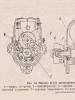
Rice. Schematic diagram of a powerful 220V mains voltage regulator.
Variable resistor R1 serves to adjust the control voltage, and resistor R2 limits the base current of the transistor. Diode VD5 protects VT1 from negative polarity voltage reaching its base. The device is connected to the network using an XP1 plug. The XS1 socket is used to connect the load.
The regulator operates as follows. After turning on the power with toggle switch S1, the mains voltage is supplied simultaneously to diodes VD1, VD2 and the primary winding of transformer T1.
In this case, a rectifier consisting of a diode bridge VD6, a capacitor C1 and a variable resistor R1 generates a control voltage that goes to the base of the transistor and opens it. If at the moment the regulator is turned on, there is a voltage of negative polarity in the network, the load current flows through the circuit VD2 - emitter-collector VT1, VD3. If the polarity of the mains voltage is positive, current flows through the circuit VD1 - collector-emitter VT1, VD4.
The value of the load current depends on the value of the control voltage based on VT1. By rotating the R1 slider and changing the value of the control voltage, the magnitude of the collector current VT1 is controlled. This current, and therefore the current flowing in the load, will be greater the higher the control voltage level, and vice versa.
When the variable resistor motor is in the extreme right position according to the diagram, the transistor will be completely open and the “dose” of electricity consumed by the load will correspond to the nominal value. If the R1 slider is moved to the extreme left position, VT1 will be locked and no current will flow through the load.
By controlling the transistor, we actually regulate the amplitude of the alternating voltage and current acting in the load. At the same time, the transistor operates in continuous mode, due to which such a regulator is free of the disadvantages inherent in thyristor devices.
Construction and details
Now let's move on to the design of the device. Diode bridges, a capacitor, resistor R2 and diode VD6 are installed on a circuit board measuring 55x35 mm, made of foil getinax or textolite 1...2 mm thick (Fig. 9.7).
The following parts can be used in the device. Transistor - KT812A(B), KT824A(B), KT828A(B), KT834A(B,V), KT840A(B), KT847A or KT856A. Diode bridges: VD1...VD4 - KTs410V or KTs412V, VD6 - KTs405 or KTs407 with any letter index; diode VD5 - series D7, D226 or D237.
Variable resistor - type SP, SPO, PPB with a power of at least 2 W, constant - BC, MJIT, OMLT, S2-23. Oxide capacitor - K50-6, K50-16. Network transformer - TVZ-1-6 from tube TVs, TS-25, TS-27 - from the Yunost TV or any other low-power one with a secondary winding voltage of 5...8 V.
The fuse is designed for a maximum current of 1 A. The toggle switch is TZ-S or any other network switch. XP1 is a standard power plug, XS1 is a socket.
All elements of the regulator are housed in a plastic case with dimensions of 150x100x80 mm. A toggle switch and a variable resistor equipped with a decorative handle are installed on the top panel of the case. The socket for connecting the load and the fuse socket are mounted on one of the side walls of the housing.
On the same side there is a hole for the power cord. A transistor, transformer and circuit board are installed at the bottom of the case. The transistor must be equipped with a radiator with a dissipation area of at least 200 cm2 and a thickness of 3...5 mm.

Rice. Printed circuit board of a powerful 220V mains voltage regulator.
The regulator does not need to be adjusted. With proper installation and serviceable parts, it begins to work immediately after being plugged into the network.
Now some recommendations for those who want to improve the device. The changes mainly concern increasing the output power of the regulator. So, for example, when using the KT856 transistor, the power consumed by the load from the network can be 150 W, for KT834 - 200 W, and for KT847 - 250 W.
If it is necessary to further increase the output power of the device, several parallel-connected transistors can be used as a control element by connecting their corresponding terminals.
Probably, in this case, the regulator will have to be equipped with a small fan for more intensive air cooling of semiconductor devices. In addition, the diode bridge VD1...VD4 will need to be replaced with four more powerful diodes, designed for an operating voltage of at least 600 V and a current value in accordance with the consumed load.
Devices of the D231...D234, D242, D243, D245...D248 series are suitable for this purpose. It will also be necessary to replace VD5 with a more powerful diode rated for current up to I A. Also, the fuse must withstand a higher current.
Such a simple, but at the same time very effective regulator can be assembled by almost anyone who can hold a soldering iron in their hands and even slightly read the diagrams. Well, this site will help you fulfill your desire. The presented regulator regulates power very smoothly without surges or dips.
Circuit of a simple triac regulator
Such a regulator can be used to regulate lighting with incandescent lamps, but also with LED lamps if you buy dimmable ones. It is easy to regulate the temperature of the soldering iron. You can continuously adjust the heating, change the rotation speed of electric motors with a wound rotor, and much more where there is a place for such a useful thing. If you have an old electric drill that does not have speed control, then by using this regulator you will improve such a useful thing.The article, with the help of photographs, descriptions and the attached video, describes in great detail the entire manufacturing process, from collecting parts to testing the finished product.

I’ll say right away that if you are not friends with your neighbors, then you don’t have to collect the C3 - R4 chain. (Joke) It serves to protect against radio interference.
All parts can be bought in China on Aliexpress. Prices are two to ten times less than in our stores.
To make this device you will need:
- R1 – resistor approximately 20 Kom, power 0.25 W;
- R2 – potentiometer approximately 500 Kom, 300 Kom to 1 Mohm is possible, but 470 Kom is better;
- R3 - resistor approximately 3 Kom, 0.25 W;
- R4 - resistor 200-300 Ohm, 0.5 W;
- C1 and C2 – capacitors 0.05 μF, 400 V;
- C3 – 0.1 μF, 400 V;
- DB3 – dinistor, found in every energy-saving lamp;
- BT139-600, regulates a current of 18 A or BT138-800, regulates a current of 12 A - triacs, but you can take any others, depending on what kind of load you need to regulate. A dinistor is also called a diac, a triac is a triac.
- The cooling radiator is selected based on the planned regulation power, but the more, the better. Without a radiator, you can regulate no more than 300 watts.
- Any terminal blocks can be installed;
- Use the breadboard as you wish, as long as everything fits in.
- Well, without a device it’s like without hands. But it’s better to use our solder. Although it is more expensive, it is much better. I haven't seen any good Chinese solder.


Let's start assembling the regulator
First, you need to think about the arrangement of parts so as to install as few jumpers as possible and do less soldering, then we very carefully check the compliance with the diagram, and then solder all the connections.


After making sure that there are no errors and placing the product in a plastic case, you can test it by connecting it to the network.

8 basic DIY regulator circuits. Top 6 brands of regulators from China. 2 schemes. 4 Most asked questions about voltage regulators.+ TEST for self-test
Voltage regulator is a specialized electrical device designed to smoothly change or adjust the voltage supplying an electrical device.
Voltage regulator
Important to remember! Devices of this type are designed to change and adjust the supply voltage, not the current. The current is regulated by the payload!
TEST:
4 questions on the topic of voltage regulators
- Why do you need a regulator:
a) Change in voltage at the output of the device.
b) Breaking the electric current circuit
- What does the regulator power depend on:
a) From the input current source and from the actuator
b) From the size of the consumer
- The main parts of the device, which you can assemble yourself:
a) Zener diode and diode
b) Triac and thyristor
- What are 0-5 volt regulators for?
a) Supply the microcircuit with a stabilized voltage
b) Limit the current consumption of electric lamps
Answers.
2 The most common DIY 0-220 volt LV circuits
Scheme No. 1.
The simplest and most convenient voltage regulator to use is regulator on thyristors connected in opposite directions. This will create a sinusoidal output signal of the required magnitude.

Input voltage up to 220V is supplied to the load through a fuse, and through the second conductor, through the power button, a sinusoidal half-wave reaches the cathode and anode thyristors VS1 and VS2. And through the variable resistor R2 the output signal is adjusted. Two diodes VD1 and VD2 leave behind only a positive half-wave arriving at the control electrode of one of thyristors, which leads to its discovery.
Important! The higher the current signal on the thyristor switch, the stronger it will open, that is, the more current it can pass through itself.
An indicator light is provided to control the input power, and a voltmeter is provided to adjust the output power.
Scheme No. 2.
A distinctive feature of this circuit is the replacement of two thyristors with one triac. This simplifies the circuit, makes it more compact and easier to manufacture.

The circuit also contains a fuse and a power button, and an adjusting resistor R3, and it controls the triac base; this is one of the few semiconductor devices with the ability to work with alternating current. Current passing through resistor R3 acquires a certain value, it will control the degree of opening triac. After this, it is rectified on the diode bridge VD1 and, through a limiting resistor, reaches the key electrode of the triac VS2. The remaining elements of the circuit, such as capacitors C1, C2, C3 and C4, serve to dampen the ripples of the input signal and filter it from extraneous noise and unregulated frequencies.
How to avoid 3 common mistakes when working with a triac.
- The letter after the triac code indicates its maximum operating voltage: A – 100V, B – 200V, C – 300V, D – 400V. Therefore, you should not take a device with the letters A and B to adjust 0-220 volts - such a triac will fail.
- A triac, like any other semiconductor device, gets very hot during operation; you should consider installing a radiator or an active cooling system.
- When using a triac in load circuits with high current consumption, it is necessary to clearly select the device for the stated purpose. For example, a chandelier with 5 bulbs of 100 watts each will consume a total current of 2 amperes. When choosing from the catalog, you need to look at the maximum operating current of the device. So triac MAC97A6 is designed for only 0.4 amperes and will not withstand such a load, while MAC228A8 is capable of passing up to 8 A and is suitable for this load.
3 Key points when making a powerful LV and current with your own hands
The device controls loads up to 3000 watts. It is built on the use of a powerful triac, and it is controlled by a gate or key dinistor.
Dinistor- this is the same as a triac, only without a control output. If triac opens and begins to pass current through itself when a control voltage appears at its base and remains open until it disappears, then dinistor will open if a potential difference above the opening barrier appears between its anode and cathode. It will remain unlocked until the current between the electrodes drops below the locking level.

As soon as a positive potential hits the control electrode, it will open and allow alternating current to pass through, and the stronger this signal is, the higher the voltage will be between its terminals, and therefore across the load. To regulate the degree of opening, an decoupling circuit is used, consisting of a dinistor VS1 and resistors R3 and R4. This circuit sets the current limit on the switch triac, and capacitors smooth out ripples on the input signal.
2 basic principles in the manufacture of 0-5 volt pH
- To convert the high input potential into a low constant potential, special LM series microcircuits are used.
- The microcircuits are powered only by direct current.
Let's consider these principles in more detail and analyze a typical regulator circuit.
LM series microcircuits are designed to reduce high DC voltage to low values. For this purpose, there are 3 terminals in the device body:
- The first pin is the input signal.
- The second pin is the output signal.
- The third output is the control electrode.
The principle of operation of the device is very simple - the input high voltage of a positive value is supplied to the input output and then converted inside the microcircuit. The degree of transformation will depend on the strength and magnitude of the signal on the control “leg”. In accordance with the master pulse, a positive voltage will be created at the output from 0 volts to the limit for this series.

The input voltage, no higher than 28 volts and must be rectified, is supplied to the circuit. You can take it from the secondary winding of the power transformer or from a high voltage regulator. After this, the positive potential is supplied to the pin of microcircuit 3. Capacitor C1 smoothes out the ripple of the input signal. Variable resistor R1 with a value of 5000 ohms sets the output signal. The higher the current it allows through itself, the higher the chip opens. The output voltage of 0-5 volts is removed from output 2 and goes to the load through smoothing capacitor C2. The higher the capacitance of the capacitor, the smoother the output.
Voltage regulator 0 - 220v
Top 4 stabilizing microcircuits 0-5 volts:
- KR1157– a domestic microcircuit, with an input signal limit of up to 25 volts and a load current of no higher than 0.1 ampere.
- 142EN5A– a microcircuit with a maximum output current of 3 amperes, no higher than 15 volts is supplied to the input.
- TS7805CZ– a device with permissible currents up to 1.5 amperes and increased input voltage up to 40 volts.
- L4960– a pulse microcircuit with a maximum load current of up to 2.5 A. The input voltage should not exceed 40 volts.
RN on 2 transistors
This type is used in circuits of particularly powerful regulators. In this case, the current to the load is also transmitted through a triac, but the key output is controlled through a cascade transistors. This is implemented like this: a variable resistor regulates the current that flows to the base of the first low-power transistor, which, through the collector-emitter junction, controls the base of the second high-power one transistor and he already opens and closes the triac. This implements the principle of very smooth control of huge load currents.

Answers to the 4 most frequently asked questions regarding regulators:
- What is the permissible deviation of the output voltage? For factory devices of large companies, the deviation will not exceed + -5%
- What does the regulator power depend on? The output power directly depends on the power source and on the triac that switches the circuit.
- What are 0-5 volt regulators for? These devices are most often used to power microcircuits and various circuit boards.
- Why do you need a 0-220 volt household regulator? They are used for smooth switching on and off of household electrical appliances.
4 DIY LV circuits and connection diagram
Let's briefly consider each of the schemes, features, and advantages.
Scheme 1.
A very simple circuit for connecting and smoothly adjusting a soldering iron. Used to prevent the soldering iron tip from burning and overheating. The circuit uses a powerful triac, which is controlled by a thyristor-variable chain resistor.

Scheme 2.
The circuit is based on the use of a phase control microcircuit of the type 1182PM1. It controls the degree of opening triac, which controls the load. They are used to smoothly control the degree of luminosity of incandescent light bulbs.

Scheme 3.
The simplest scheme for regulating the heat of a soldering iron tip. Made according to a very compact design using easily accessible components. The load is controlled by one thyristor, the degree of activation of which is regulated by a variable resistor. There is also a diode to protect against reverse voltage. The thyristor,
Chinese LV 220 volt
Nowadays, goods from China have become quite a popular topic, and Chinese voltage regulators do not lag behind the general trend. Let's look at the most popular Chinese models and compare their main characteristics.
It is possible to choose any regulator specifically for your requirements and needs. On average, one watt of useful power costs less than 20 cents, and this is a very competitive price. But still, it is worth paying attention to the quality of parts and assembly; for goods from China it still remains very low.