Microcircuit for monitoring battery charge. Circuits for protecting Li-ion batteries from overdischarge (discharge controllers). NCP1835B - microcircuit for charging Li-Ion and Li-Pol batteries
Assessing the characteristics of a particular charger is difficult without understanding how an exemplary charge of a li-ion battery should actually proceed. Therefore, before moving directly to the diagrams, let's remember a little theory.
What are lithium batteries?
Depending on what material the positive electrode of a lithium battery is made of, there are several varieties:
- with lithium cobaltate cathode;
- with a cathode based on lithiated iron phosphate;
- based on nickel-cobalt-aluminium;
- based on nickel-cobalt-manganese.
All of these batteries have their own characteristics, but since these nuances are not of fundamental importance for the general consumer, they will not be considered in this article.
Also, all li-ion batteries are produced in various sizes and form factors. They can be either cased (for example, the popular 18650 today) or laminated or prismatic (gel-polymer batteries). The latter are hermetically sealed bags made of a special film, which contain electrodes and electrode mass.
The most common sizes of li-ion batteries are shown in the table below (all of them have a nominal voltage of 3.7 volts):
| Designation | Standard size | Similar size |
|---|---|---|
| XXYY0, Where XX- indication of diameter in mm, YY- length value in mm, 0 - reflects the design in the form of a cylinder |
10180 | 2/5 AAA |
| 10220 | 1/2 AAA (Ø corresponds to AAA, but half the length) | |
| 10280 | ||
| 10430 | AAA | |
| 10440 | AAA | |
| 14250 | 1/2 AA | |
| 14270 | Ø AA, length CR2 | |
| 14430 | Ø 14 mm (same as AA), but shorter length | |
| 14500 | AA | |
| 14670 | ||
| 15266, 15270 | CR2 | |
| 16340 | CR123 | |
| 17500 | 150S/300S | |
| 17670 | 2xCR123 (or 168S/600S) | |
| 18350 | ||
| 18490 | ||
| 18500 | 2xCR123 (or 150A/300P) | |
| 18650 | 2xCR123 (or 168A/600P) | |
| 18700 | ||
| 22650 | ||
| 25500 | ||
| 26500 | WITH | |
| 26650 | ||
| 32650 | ||
| 33600 | D | |
| 42120 |
Internal electrochemical processes proceed in the same way and do not depend on the form factor and design of the battery, so everything said below applies equally to all lithium batteries.
How to properly charge lithium-ion batteries
The most correct way to charge lithium batteries is to charge in two stages. This is the method Sony uses in all of its chargers. Despite the more complex charge controller, this ensures a more complete charge of li-ion batteries without reducing their service life.
Here we are talking about a two-stage charge profile for lithium batteries, abbreviated as CC/CV (constant current, constant voltage). There are also options with pulse and step currents, but they are not discussed in this article. You can read more about charging with pulsed current.
So, let's look at both stages of charging in more detail.
1. At the first stage A constant charging current must be ensured. The current value is 0.2-0.5C. For accelerated charging, it is allowed to increase the current to 0.5-1.0C (where C is the battery capacity).
For example, for a battery with a capacity of 3000 mAh, the nominal charge current at the first stage is 600-1500 mA, and the accelerated charge current can be in the range of 1.5-3A.
To ensure a constant charging current of a given value, the charger circuit must be able to increase the voltage at the battery terminals. In fact, at the first stage the charger works as a classic current stabilizer.
Important: If you plan to charge batteries with a built-in protection board (PCB), then when designing the charger circuit you need to make sure that the open circuit voltage of the circuit can never exceed 6-7 volts. Otherwise, the protection board may be damaged.
At the moment when the voltage on the battery rises to 4.2 volts, the battery will gain approximately 70-80% of its capacity (the specific capacity value will depend on the charging current: with accelerated charging it will be a little less, with a nominal charge - a little more). This moment marks the end of the first stage of charging and serves as a signal for the transition to the second (and final) stage.
2. Second charge stage- this is charging the battery with a constant voltage, but a gradually decreasing (falling) current.
At this stage, the charger maintains a voltage of 4.15-4.25 volts on the battery and controls the current value.
As the capacity increases, the charging current will decrease. As soon as its value decreases to 0.05-0.01C, the charging process is considered complete.
An important nuance of the correct charger operation is its complete disconnection from the battery after charging is complete. This is due to the fact that for lithium batteries it is extremely undesirable for them to remain under high voltage for a long time, which is usually provided by the charger (i.e. 4.18-4.24 volts). This leads to accelerated degradation of the chemical composition of the battery and, as a consequence, a decrease in its capacity. Long-term stay means tens of hours or more.
During the second stage of charging, the battery manages to gain approximately 0.1-0.15 more of its capacity. The total battery charge thus reaches 90-95%, which is an excellent indicator.
We looked at two main stages of charging. However, coverage of the issue of charging lithium batteries would be incomplete if another charging stage were not mentioned - the so-called. precharge.
Preliminary charge stage (precharge)- this stage is used only for deeply discharged batteries (below 2.5 V) to bring them to normal operating mode.
At this stage, the charge is provided with a reduced constant current until the battery voltage reaches 2.8 V.
The preliminary stage is necessary to prevent swelling and depressurization (or even explosion with fire) of damaged batteries that have, for example, an internal short circuit between the electrodes. If a large charge current is immediately passed through such a battery, this will inevitably lead to its heating, and then it depends.
Another benefit of precharging is pre-heating the battery, which is important when charging at low ambient temperatures (in an unheated room during the cold season).
Intelligent charging should be able to monitor the voltage on the battery during the preliminary charging stage and, if the voltage does not rise for a long time, draw a conclusion that the battery is faulty.
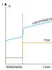
All stages of charging a lithium-ion battery (including the pre-charge stage) are schematically depicted in this graph: 
Exceeding the rated charging voltage by 0.15V can reduce the battery life by half. Lowering the charge voltage by 0.1 volt reduces the capacity of a charged battery by about 10%, but significantly extends its service life. The voltage of a fully charged battery after removing it from the charger is 4.1-4.15 volts.
Let me summarize the above and outline the main points:
1. What current should I use to charge a li-ion battery (for example, 18650 or any other)?
The current will depend on how quickly you would like to charge it and can range from 0.2C to 1C.
For example, for a battery size 18650 with a capacity of 3400 mAh, the minimum charge current is 680 mA, and the maximum is 3400 mA.
2. How long does it take to charge, for example, the same 18650 batteries?
The charging time directly depends on the charging current and is calculated using the formula:
T = C / I charge.
For example, the charging time for our 3400 mAh battery with a current of 1A will be about 3.5 hours.
3. How to properly charge a lithium polymer battery?
All lithium batteries charge the same way. It doesn't matter whether it is lithium polymer or lithium ion. For us, consumers, there is no difference.
What is a protection board?
The protection board (or PCB - power control board) is designed to protect against short circuit, overcharge and overdischarge of the lithium battery. As a rule, overheating protection is also built into the protection modules.
For safety reasons, it is prohibited to use lithium batteries in household appliances unless they have a built-in protection board. That's why all cell phone batteries always have a PCB board. The battery output terminals are located directly on the board: 
These boards use a six-legged charge controller on a specialized device (JW01, JW11, K091, G2J, G3J, S8210, S8261, NE57600 and other analogues). The task of this controller is to disconnect the battery from the load when the battery is completely discharged and disconnect the battery from charging when it reaches 4.25V.
Here, for example, is a diagram of the BP-6M battery protection board that was supplied with old Nokia phones: 
If we talk about 18650, they can be produced either with or without a protection board. The protection module is located near the negative terminal of the battery. 

The board increases the length of the battery by 2-3 mm. 
Batteries without a PCB module are usually included in batteries that come with their own protection circuits.
Any battery with protection can easily turn into a battery without protection; you just need to gut it. ![]()
Today, the maximum capacity of the 18650 battery is 3400 mAh. Batteries with protection must have a corresponding designation on the case ("Protected"). 
Do not confuse the PCB board with the PCM module (PCM - power charge module). If the former serve only the purpose of protecting the battery, then the latter are designed to control the charging process - they limit the charge current at a given level, control the temperature and, in general, ensure the entire process. The PCM board is what we call a charge controller.
I hope now there are no questions left, how to charge an 18650 battery or any other lithium battery? Then we move on to a small selection of ready-made circuit solutions for chargers (the same charge controllers).
Charging schemes for li-ion batteries
All circuits are suitable for charging any lithium battery; all that remains is to decide on the charging current and the element base.
LM317
Diagram of a simple charger based on the LM317 chip with a charge indicator: 
The circuit is the simplest, the whole setup comes down to setting the output voltage to 4.2 volts using trimming resistor R8 (without a connected battery!) and setting the charging current by selecting resistors R4, R6. The power of resistor R1 is at least 1 Watt.
As soon as the LED goes out, the charging process can be considered completed (the charging current will never decrease to zero). It is not recommended to keep the battery on this charge for a long time after it is fully charged.
The lm317 microcircuit is widely used in various voltage and current stabilizers (depending on the connection circuit). It is sold on every corner and costs pennies (you can take 10 pieces for only 55 rubles).
LM317 comes in different housings: 
Pin assignment (pinout): 
Analogues of the LM317 chip are: GL317, SG31, SG317, UC317T, ECG1900, LM31MDT, SP900, KR142EN12, KR1157EN1 (the last two are domestically produced).
The charging current can be increased to 3A if you take LM350 instead of LM317. It will, however, be more expensive - 11 rubles/piece.
The printed circuit board and circuit assembly are shown below: 

The old Soviet transistor KT361 can be replaced with a similar pnp transistor (for example, KT3107, KT3108 or bourgeois 2N5086, 2SA733, BC308A). It can be removed altogether if the charge indicator is not needed.
Disadvantage of the circuit: the supply voltage must be in the range of 8-12V. This is due to the fact that for normal operation of the LM317 chip, the difference between the battery voltage and the supply voltage must be at least 4.25 Volts. Thus, it will not be possible to power it from the USB port.
MAX1555 or MAX1551
MAX1551/MAX1555 are specialized chargers for Li+ batteries, capable of operating from USB or from a separate power adapter (for example, a phone charger).
 The only difference between these microcircuits is that MAX1555 produces a signal to indicate the charging process, and MAX1551 produces a signal that the power is on. Those. 1555 is still preferable in most cases, so 1551 is now difficult to find on sale.
A detailed description of these microcircuits from the manufacturer is.
The maximum input voltage from the DC adapter is 7 V, when powered by USB - 6 V. When the supply voltage drops to 3.52 V, the microcircuit turns off and charging stops.
The microcircuit itself detects at which input the supply voltage is present and connects to it. If the power is supplied via the USB bus, then the maximum charging current is limited to 100 mA - this allows you to plug the charger into the USB port of any computer without fear of burning the south bridge.
When powered by a separate power supply, the typical charging current is 280 mA.
The chips have built-in overheating protection. But even in this case, the circuit continues to operate, reducing the charge current by 17 mA for each degree above 110 ° C.
There is a pre-charge function (see above): as long as the battery voltage is below 3V, the microcircuit limits the charge current to 40 mA.
The microcircuit has 5 pins. Here is a typical connection diagram: 
If there is a guarantee that the voltage at the output of your adapter cannot under any circumstances exceed 7 volts, then you can do without the 7805 stabilizer.
The USB charging option can be assembled, for example, on this one. 
The microcircuit does not require either external diodes or external transistors. In general, of course, gorgeous little things! Only they are too small and inconvenient to solder. And they are also expensive ().
LP2951
The LP2951 stabilizer is manufactured by National Semiconductors (). It provides the implementation of a built-in current limiting function and allows you to generate a stable charge voltage level for a lithium-ion battery at the output of the circuit.
The charge voltage is 4.08 - 4.26 volts and is set by resistor R3 when the battery is disconnected. The voltage is kept very precisely.
The charge current is 150 - 300mA, this value is limited by the internal circuits of the LP2951 chip (depending on the manufacturer).
Use the diode with a small reverse current. For example, it can be any of the 1N400X series that you can purchase. The diode is used as a blocking diode to prevent reverse current from the battery into the LP2951 chip when the input voltage is turned off. 
This charger produces a fairly low charging current, so any 18650 battery can charge overnight.
The microcircuit can be purchased both in a DIP package and in a SOIC package (costs about 10 rubles per piece).
MCP73831
The chip allows you to create the right chargers, and it’s also cheaper than the much-hyped MAX1555. 
A typical connection diagram is taken from: 
An important advantage of the circuit is the absence of low-resistance powerful resistors that limit the charge current. Here the current is set by a resistor connected to the 5th pin of the microcircuit. Its resistance should be in the range of 2-10 kOhm.
The assembled charger looks like this: 
The microcircuit heats up quite well during operation, but this does not seem to bother it. It fulfills its function.
Here is another version of a printed circuit board with an SMD LED and a micro-USB connector: 
LTC4054 (STC4054)
Very simple scheme, great option! Allows charging with current up to 800 mA (see). True, it tends to get very hot, but in this case the built-in overheating protection reduces the current. 
The circuit can be significantly simplified by throwing out one or even both LEDs with a transistor. Then it will look like this (you must admit, it couldn’t be simpler: a pair of resistors and one condenser): 
One of the printed circuit board options is available at . The board is designed for elements of standard size 0805.
I=1000/R. You shouldn’t set a high current right away; first see how hot the microcircuit gets. For my purposes, I took a 2.7 kOhm resistor, and the charge current turned out to be about 360 mA.
It is unlikely that it will be possible to adapt a radiator to this microcircuit, and it is not a fact that it will be effective due to the high thermal resistance of the crystal-case junction. The manufacturer recommends making the heat sink “through the leads” - making the traces as thick as possible and leaving the foil under the chip body. In general, the more “earth” foil left, the better.
By the way, most of the heat is dissipated through the 3rd leg, so you can make this trace very wide and thick (fill it with excess solder). 
The LTC4054 chip package may be labeled LTH7 or LTADY.
LTH7 differs from LTADY in that the first can lift a very low battery (on which the voltage is less than 2.9 volts), while the second cannot (you need to swing it separately).
The chip turned out to be very successful, so it has a bunch of analogues: STC4054, MCP73831, TB4054, QX4054, TP4054, SGM4054, ACE4054, LP4054, U4054, BL4054, WPM4054, IT4504, Y1880, PT6102, PT6181, 2, HX6001, LC6000, LN5060, CX9058, EC49016, CYT5026, Q7051. Before using any of the analogues, check the datasheets.
TP4056
The microcircuit is made in a SOP-8 housing (see), it has a metal heat sink on its belly that is not connected to the contacts, which allows for more efficient heat removal. Allows you to charge the battery with a current of up to 1A (the current depends on the current-setting resistor). 
The connection diagram requires the bare minimum of hanging elements: 
The circuit implements the classical charging process - first charging with a constant current, then with a constant voltage and a falling current. Everything is scientific. If you look at charging step by step, you can distinguish several stages:
- Monitoring the voltage of the connected battery (this happens all the time).
- Precharge phase (if the battery is discharged below 2.9 V). Charge with a current of 1/10 from the one programmed by the resistor R prog (100 mA at R prog = 1.2 kOhm) to a level of 2.9 V.
- Charging with a maximum constant current (1000 mA at R prog = 1.2 kOhm);
- When the battery reaches 4.2 V, the voltage on the battery is fixed at this level. A gradual decrease in the charging current begins.
- When the current reaches 1/10 of the one programmed by the resistor R prog (100 mA at R prog = 1.2 kOhm), the charger turns off.
- After charging is complete, the controller continues monitoring the battery voltage (see point 1). The current consumed by the monitoring circuit is 2-3 µA. After the voltage drops to 4.0V, charging starts again. And so on in a circle.
The charge current (in amperes) is calculated by the formula I=1200/R prog. The permissible maximum is 1000 mA.
A real charging test with a 3400 mAh 18650 battery is shown in the graph: 
The advantage of the microcircuit is that the charge current is set by just one resistor. Powerful low-resistance resistors are not required. Plus there is an indicator of the charging process, as well as an indication of the end of charging. When the battery is not connected, the indicator blinks every few seconds.
The supply voltage of the circuit should be within 4.5...8 volts. The closer to 4.5V, the better (so the chip heats up less).
The first leg is used to connect a temperature sensor built into the lithium-ion battery (usually the middle terminal of a cell phone battery). If the voltage at the output is below 45% or above 80% of the supply voltage, charging is suspended. If you don't need temperature control, just plant that foot on the ground.
Attention! This circuit has one significant drawback: the absence of a battery reverse polarity protection circuit. In this case, the controller is guaranteed to burn out due to exceeding the maximum current. In this case, the supply voltage of the circuit directly goes to the battery, which is very dangerous.
The signet is simple and can be done in an hour on your knee. If time is of the essence, you can order ready-made modules. Some manufacturers of ready-made modules add protection against overcurrent and overdischarge (for example, you can choose which board you need - with or without protection, and with which connector). 
You can also find ready-made boards with a contact for a temperature sensor. Or even a charging module with several parallel TP4056 microcircuits to increase the charging current and with reverse polarity protection (example).
LTC1734
Also a very simple scheme. The charging current is set by resistor R prog (for example, if you install a 3 kOhm resistor, the current will be 500 mA).
Microcircuits are usually marked on the case: LTRG (they can often be found in old Samsung phones). 
Any pnp transistor is suitable, the main thing is that it is designed for a given charging current.
There is no charge indicator on the indicated diagram, but on the LTC1734 it is said that pin “4” (Prog) has two functions - setting the current and monitoring the end of the battery charge. For example, a circuit with control of the end of charge using the LT1716 comparator is shown. 
The LT1716 comparator in this case can be replaced with a cheap LM358.
TL431 + transistor
It is probably difficult to come up with a circuit using more affordable components. The most difficult thing here is to find the TL431 reference voltage source. But they are so common that they are found almost everywhere (rarely does a power source do without this microcircuit). 
Well, the TIP41 transistor can be replaced with any other one with a suitable collector current. Even the old Soviet KT819, KT805 (or less powerful KT815, KT817) will do.
Setting up the circuit comes down to setting the output voltage (without a battery!!!) using a trim resistor at 4.2 volts. Resistor R1 sets the maximum value of the charging current.
This circuit fully implements the two-stage process of charging lithium batteries - first charging with direct current, then moving to the voltage stabilization phase and smoothly reducing the current to almost zero. The only drawback is the poor repeatability of the circuit (it is capricious in setup and demanding on the components used).
MCP73812
There is another undeservedly neglected microcircuit from Microchip - MCP73812 (see). Based on it, a very budget charging option is obtained (and inexpensive!). The whole body kit is just one resistor!
By the way, the microcircuit is made in a solder-friendly package - SOT23-5. 
The only negative is that it gets very hot and there is no charge indication. It also somehow doesn’t work very reliably if you have a low-power power source (which causes a voltage drop). 
In general, if the charge indication is not important for you, and a current of 500 mA suits you, then the MCP73812 is a very good option.
NCP1835
A fully integrated solution is offered - NCP1835B, providing high stability of the charging voltage (4.2 ±0.05 V).
Perhaps the only drawback of this microcircuit is its too miniature size (DFN-10 case, size 3x3 mm). Not everyone can provide high-quality soldering of such miniature elements. 
Among the undeniable advantages I would like to note the following:
- Minimum number of body parts.
- Possibility of charging a completely discharged battery (precharge current 30 mA);
- Determining the end of charging.
- Programmable charging current - up to 1000 mA.
- Charge and error indication (capable of detecting non-chargeable batteries and signaling this).
- Protection against long-term charging (by changing the capacitance of the capacitor C t, you can set the maximum charging time from 6.6 to 784 minutes).

The cost of the microcircuit is not exactly cheap, but also not so high (~$1) that you can refuse to use it. If you are comfortable with a soldering iron, I would recommend choosing this option.
A more detailed description is in.
Can I charge a lithium-ion battery without a controller?
Yes, you can. However, this will require close control of the charging current and voltage.
In general, it will not be possible to charge a battery, for example, our 18650, without a charger. You still need to somehow limit the maximum charge current, so at least the most primitive memory will still be required.
The simplest charger for any lithium battery is a resistor connected in series with the battery: 
The resistance and power dissipation of the resistor depend on the voltage of the power source that will be used for charging.
As an example, let's calculate a resistor for a 5 Volt power supply. We will charge an 18650 battery with a capacity of 2400 mAh.
So, at the very beginning of charging, the voltage drop across the resistor will be:
U r = 5 - 2.8 = 2.2 Volts
Let's say our 5V power supply is rated for a maximum current of 1A. The circuit will consume the highest current at the very beginning of the charge, when the voltage on the battery is minimal and amounts to 2.7-2.8 Volts.
Attention: these calculations do not take into account the possibility that the battery may be very deeply discharged and the voltage on it may be much lower, even to zero.
Thus, the resistor resistance required to limit the current at the very beginning of the charge at 1 Ampere should be:
R = U / I = 2.2 / 1 = 2.2 Ohm
Resistor power dissipation:
P r = I 2 R = 1*1*2.2 = 2.2 W
At the very end of the battery charge, when the voltage on it approaches 4.2 V, the charge current will be:
I charge = (U ip - 4.2) / R = (5 - 4.2) / 2.2 = 0.3 A
That is, as we see, all values do not go beyond the permissible limits for a given battery: the initial current does not exceed the maximum permissible charging current for a given battery (2.4 A), and the final current exceeds the current at which the battery no longer gains capacity ( 0.24 A).
The main disadvantage of such charging is the need to constantly monitor the voltage on the battery. And manually turn off the charge as soon as the voltage reaches 4.2 Volts. The fact is that lithium batteries tolerate even short-term overvoltage very poorly - the electrode masses begin to quickly degrade, which inevitably leads to loss of capacity. At the same time, all the prerequisites for overheating and depressurization are created.
If your battery has a built-in protection board, which was discussed just above, then everything becomes simpler. When a certain voltage is reached on the battery, the board itself will disconnect it from the charger. However, this charging method has significant disadvantages, which we discussed in.
The protection built into the battery will not allow it to be overcharged under any circumstances. All you have to do is control the charge current so that it does not exceed the permissible values for a given battery (protection boards cannot limit the charge current, unfortunately).
Charging using a laboratory power supply
If you have a power supply with current protection (limitation), then you are saved! Such a power source is already a full-fledged charger that implements the correct charge profile, which we wrote about above (CC/CV).
 All you need to do to charge li-ion is set the power supply to 4.2 volts and set the desired current limit. And you can connect the battery.
Initially, when the battery is still discharged, the laboratory power supply will operate in current protection mode (i.e., it will stabilize the output current at a given level). Then, when the voltage on the bank rises to the set 4.2V, the power supply will switch to voltage stabilization mode, and the current will begin to drop.
When the current drops to 0.05-0.1C, the battery can be considered fully charged.
As you can see, the laboratory power supply is an almost ideal charger! The only thing it can’t do automatically is make a decision to fully charge the battery and turn off. But this is a small thing that you shouldn’t even pay attention to.
How to charge lithium batteries?
And if we are talking about a disposable battery that is not intended for recharging, then the correct (and only correct) answer to this question is NO.
The fact is that any lithium battery (for example, the common CR2032 in the form of a flat tablet) is characterized by the presence of an internal passivating layer that covers the lithium anode. This layer prevents a chemical reaction between the anode and the electrolyte. And the supply of external current destroys the above protective layer, leading to damage to the battery.
By the way, if we talk about the non-rechargeable CR2032 battery, then the LIR2032, which is very similar to it, is already a full-fledged battery. It can and should be charged. Only its voltage is not 3, but 3.6V.
How to charge lithium batteries (be it a phone battery, 18650 or any other li-ion battery) was discussed at the beginning of the article.
It's no secret that Li-ion batteries do not like deep discharge. This causes them to wither and wither, and also increase internal resistance and lose capacity. Some specimens (those with protection) can even plunge into deep hibernation, from where it is quite problematic to pull them out. Therefore, when using lithium batteries, it is necessary to somehow limit their maximum discharge.
To do this, special circuits are used that disconnect the battery from the load at the right time. Sometimes such circuits are called discharge controllers.
Because The discharge controller does not control the magnitude of the discharge current; strictly speaking, it is not a controller of any kind. In fact, this is an established but incorrect name for deep discharge protection circuits.
Contrary to popular belief, the built-in batteries (PCB boards or PCM modules) are not designed to limit the charge/discharge current, or to timely disconnect the load when fully discharged, or to correctly determine the end of charging.
Firstly, Protection boards, in principle, are not capable of limiting the charge or discharge current. This should be handled by the memory department. The maximum they can do is turn off the battery when there is a short circuit in the load or when it overheats.
Secondly, Most protection modules turn off the li-ion battery at a voltage of 2.5 Volts or even less. And for the vast majority of batteries, this is a very strong discharge; this should not be allowed at all.
Third, The Chinese are riveting these modules in the millions... Do you really believe that they use high-quality precision components? Or that someone tests and adjusts them before installing them in batteries? Of course, this is not true. When producing Chinese motherboards, only one principle is strictly observed: the cheaper, the better. Therefore, if the protection disconnects the battery from the charger exactly at 4.2 ± 0.05 V, then this is more likely a happy accident than a pattern.
It’s good if you got a PCB module that will operate a little earlier (for example, at 4.1V). Then the battery simply won’t reach ten percent of its capacity and that’s it. It is much worse if the battery is constantly recharged, for example, to 4.3V. Then the service life is reduced and the capacity drops and, in general, may swell.
It is IMPOSSIBLE to use the protection boards built into lithium-ion batteries as discharge limiters! And as charge limiters too. These boards are intended only for emergency battery disconnection in case of emergency situations.
Therefore, separate circuits for limiting charge and/or protecting against too deep discharge are needed.
We looked at simple chargers based on discrete components and specialized integrated circuits in. And today we’ll talk about the solutions that exist today to protect a lithium battery from too much discharge.
To begin with, I propose a simple and reliable Li-ion overdischarge protection circuit, consisting of only 6 elements. 
The ratings indicated in the diagram will result in the batteries being disconnected from the load when the voltage drops to ~10 Volts (I made protection for 3 series-connected 18650 batteries in my metal detector). You can set your own shutdown threshold by selecting resistor R3.
By the way, the full discharge voltage of a Li-ion battery is 3.0 V and no less.
A field chip (like the one in the diagram or something similar) can be dug out from an old computer motherboard; usually there are several of them at once. TL-ku, by the way, can also be taken from there.
Capacitor C1 is needed for the initial startup of the circuit when the switch is turned on (it briefly pulls the gate T1 to minus, which opens the transistor and powers the voltage divider R3, R2). Further, after charging C1, the voltage required to unlock the transistor is maintained by the TL431 microcircuit.
Attention! The IRF4905 transistor indicated in the diagram will perfectly protect three lithium-ion batteries connected in series, but is completely unsuitable for protecting one 3.7 Volt bank. It is said how to determine for yourself whether a field-effect transistor is suitable or not.
The downside of this circuit: in the event of a short circuit in the load (or too much current consumed), the field-effect transistor will not close immediately. The reaction time will depend on the capacitance of capacitor C1. And it is quite possible that during this time something will have time to burn out properly. A circuit that instantly responds to a short load under load is presented below: 
Switch SA1 is needed to “restart” the circuit after the protection has tripped. If the design of your device provides for removing the battery to charge it (in a separate charger), then this switch is not needed.
The resistance of resistor R1 must be such that the TL431 stabilizer reaches operating mode at a minimum battery voltage - it is selected in such a way that the anode-cathode current is at least 0.4 mA. This gives rise to another drawback of this circuit - after the protection is triggered, the circuit continues to consume energy from the battery. The current, although small, is quite enough to completely drain a small battery in just a couple of months.
The diagram below for homemade control of the discharge of lithium batteries is free from this drawback. When the protection is triggered, the current consumed by the device is so small that my tester does not even detect it. 
Below is a more modern version of the lithium battery discharge limiter using the TL431 stabilizer. This, firstly, allows you to easily and simply set the desired response threshold, and secondly, the circuit has high temperature stability and clear shutdown. Clap and that's it! 
Getting TL-ku today is not a problem at all, they are sold for 5 kopecks per bunch. Resistor R1 does not need to be installed (in some cases it is even harmful). Trimmer R6, which sets the response voltage, can be replaced with a chain of constant resistors with selected resistances.
To exit the blocking mode, you need to charge the battery above the protection threshold, and then press the S1 “Reset” button.
The inconvenience of all the above schemes is that to resume operation of the schemes after going into protection, operator intervention is required (turn SA1 on and off or press a button). This is the price to pay for simplicity and low power consumption in lock mode.
The simplest li-ion overdischarge protection circuit, devoid of all disadvantages (well, almost all) is shown below: 
The principle of operation of this circuit is very similar to the first two (at the very beginning of the article), but there is no TL431 microcircuit, and therefore its own current consumption can be reduced to very small values - about ten microamps. A switch or reset button is also not needed; the circuit will automatically connect the battery to the load as soon as the voltage across it exceeds a preset threshold value.
Capacitor C1 suppresses false alarms when operating on a pulsed load. Any low-power diodes will do; it is their characteristics and quantity that determine the operating voltage of the circuit (you will have to select it locally).
Any suitable n-channel field effect transistor can be used. The main thing is that it can withstand the load current without straining and be able to open at low gate-source voltage. For example, P60N03LDG, IRLML6401 or similar (see).
The above circuit is good for everyone, but there is one unpleasant moment - the smooth closing of the field-effect transistor. This occurs due to the flatness of the initial section of the current-voltage characteristic of the diodes.
This drawback can be eliminated with the help of modern element base, namely with the help of micro-power voltage detectors (power monitors with extremely low power consumption). The next circuit for protecting lithium from deep discharge is presented below: 
MCP100 microcircuits are available in both DIP packages and planar versions. For our needs, a 3-volt option is suitable - MCP100T-300i/TT. Typical current consumption in blocking mode is 45 µA. The cost for small wholesale is about 16 rubles/piece.
It’s even better to use a BD4730 monitor instead of the MCP100, because it has a direct output and, therefore, it will be necessary to exclude transistor Q1 from the circuit (connect the output of the microcircuit directly to the gate of Q2 and resistor R2, while increasing R2 to 47 kOhm).
The circuit uses a micro-ohm p-channel MOSFET IRF7210, which easily switches currents of 10-12 A. The field switch is fully open already at a gate voltage of about 1.5 V, and in the open state it has negligible resistance (less than 0.01 Ohm)! In short, a very cool transistor. And, most importantly, not too expensive.
In my opinion, the last scheme is the closest to the ideal. If I had unlimited access to radio components, I would choose this one.
A small change in the circuit allows you to use an N-channel transistor (then it is connected to the negative load circuit): 
BD47xx power supply monitors (supervisors, detectors) are a whole line of microcircuits with response voltages from 1.9 to 4.6 V in steps of 100 mV, so you can always choose them to suit your purposes.
A small retreat
Any of the above circuits can be connected to a battery of several batteries (after some adjustment, of course). However, if the banks have different capacities, then the weakest of the batteries will constantly go into a deep discharge long before the circuit operates. Therefore, in such cases, it is always recommended to use batteries not only of the same capacity, but preferably from the same batch.
And although such protection has been working flawlessly in my metal detector for two years now, it would still be much more correct to monitor the voltage on each battery personally.
Always use your personal Li-ion battery discharge controller for each jar. Then any of your batteries will serve you happily ever after.
How to choose a suitable field-effect transistor
In all of the above schemes for protecting lithium-ion batteries from deep discharge, MOSFETs operating in switching mode are used. The same transistors are usually used in overcharge protection circuits, short-circuit protection circuits, and in other cases where load control is required.
Of course, in order for the circuit to work as it should, the field-effect transistor must meet certain requirements. First, we will decide on these requirements, and then we will take a couple of transistors and use their datasheets (technical characteristics) to determine whether they are suitable for us or not.
Attention! We will not consider the dynamic characteristics of FETs, such as switching speed, gate capacitance and maximum pulsed drain current. These parameters become critically important when the transistor operates at high frequencies (inverters, generators, PWM modulators, etc.), however, discussion of this topic is beyond the scope of this article.
So, we must immediately decide on the circuit that we want to assemble. Hence the first requirement for a field-effect transistor - it must be the right type(either N- or P-channel). This is the first.
Let's assume that the maximum current (load current or charge current - it doesn't matter) will not exceed 3A. This leads to the second requirement - a field worker must withstand such current for a long time.
Third. Let's say our circuit will protect the 18650 battery from deep discharge (one bank). Therefore, we can immediately decide on the operating voltages: from 3.0 to 4.3 Volts. Means, maximum permissible drain-source voltage U ds should be more than 4.3 Volts.
However, the last statement is true only if only one lithium battery bank is used (or several connected in parallel). If, to power your load, a battery of several batteries connected in series is used, then the maximum drain-source voltage of the transistor must exceed the total voltage of the entire battery.
Here is a picture explaining this point: 
As can be seen from the diagram, for a battery of 3 18650 batteries connected in series, in the protection circuits of each bank it is necessary to use field devices with a drain-to-source voltage U ds > 12.6V (in practice, you need to take it with some margin, for example, 10%).
At the same time, this means that the field-effect transistor must be able to open completely (or at least strongly enough) already at a gate-source voltage U gs of less than 3 Volts. In fact, it is better to focus on a lower voltage, for example, 2.5 Volts, so that there is a margin.
For a rough (initial) estimate, you can look in the datasheet at the “Cut-off voltage” indicator ( Gate Threshold Voltage) is the voltage at which the transistor is on the threshold of opening. This voltage is typically measured when the drain current reaches 250 µA.
It is clear that the transistor cannot be operated in this mode, because its output impedance is still too high, and it will simply burn out due to excess power. That's why The transistor cut-off voltage must be less than the operating voltage of the protection circuit. And the smaller it is, the better.
In practice, to protect one can of a lithium-ion battery, you should select a field-effect transistor with a cutoff voltage of no more than 1.5 - 2 Volts.
Thus, the main requirements for field-effect transistors are as follows:
- transistor type (p- or n-channel);
- maximum permissible drain current;
- the maximum permissible drain-source voltage U ds (remember how our batteries will be connected - in series or in parallel);
- low output resistance at a certain gate-source voltage U gs (to protect one Li-ion can, you should focus on 2.5 Volts);
- maximum permissible power dissipation.
Now let's look at specific examples. For example, we have at our disposal the transistors IRF4905, IRL2505 and IRLMS2002. Let's take a closer look at them.
Example 1 - IRF4905
 We open the datasheet and see that this is a transistor with a p-type channel (p-channel). If we are satisfied with this, we look further.
The maximum drain current is 74A. In excess, of course, but it fits.
Drain-source voltage - 55V. According to the conditions of the problem, we have only one bank of lithium, so the voltage is even greater than required.
Next, we are interested in the question of what the drain-source resistance will be when the opening voltage at the gate is 2.5V. We look at the datasheet and don’t immediately see this information. But we see that the cutoff voltage U gs(th) lies in the range of 2...4 Volts. We are categorically not happy with this.
The last requirement is not met, so discard the transistor.
Example 2 - IRL2505
 Here is his datasheet. We look and immediately see that this is a very powerful N-channel field device. Drain current - 104A, drain-source voltage - 55V. So far everything is fine.
Check the voltage V gs(th) - maximum 2.0 V. Excellent!
But let's see what resistance the transistor will have at a gate-source voltage = 2.5 volts. Let's look at the chart: 
It turns out that with a gate voltage of 2.5V and a current through the transistor of 3A, a voltage of 3V will drop across it. In accordance with Ohm's law, its resistance at this moment will be 3V/3A=1Ohm.
Thus, when the voltage on the battery bank is about 3 Volts, it simply cannot supply 3A to the load, since for this the total load resistance, together with the drain-source resistance of the transistor, must be 1 Ohm. And we only have one transistor that already has a resistance of 1 ohm.
In addition, with such an internal resistance and a given current, the transistor will release power (3 A) 2 * 3 Ohm = 9 W. Therefore, you will need to install a radiator (a TO-220 case without a radiator can dissipate somewhere around 0.5...1 W).
An additional alarm bell should be the fact that the minimum gate voltage for which the manufacturer specified the output resistance of the transistor is 4V.
This seems to hint that the operation of the field worker at a voltage U gs less than 4 V was not envisaged.
Considering all of the above, discard the transistor.
Example 3 - IRLMS2002
 So, let's take our third candidate out of the box. And immediately look at its performance characteristics.
N-type channel, let's say everything is in order.
Maximum drain current - 6.5 A. Suitable.
The maximum permissible drain-source voltage V dss = 20V. Great.
Cut-off voltage - max. 1.2 Volts. Still alright.
To find out the output resistance of this transistor, we don’t even have to look at the graphs (as we did in the previous case) - the required resistance is immediately given in the table just for our gate voltage.
Protection of lithium-ion batteries (Li-ion). I think that many of you know that, for example, inside a mobile phone battery there is also a protection circuit (protection controller), which ensures that the battery (cell, bank, etc....) is not overcharged above a voltage of 4.2 V , or discharged less than 2...3 V. Also, the protection circuit saves from short circuits by disconnecting the can itself from the consumer at the moment of a short circuit. When the battery reaches the end of its service life, you can remove the protection controller board from it and throw away the battery itself. The protection board can be useful for repairing another battery, for protecting a can (which does not have protection circuits), or you can simply connect the board to the power supply and experiment with it.
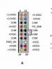
I had many protection boards for batteries that had become unusable. But a search on the Internet for the markings of the microcircuits yielded nothing, as if the microcircuits were classified. On the Internet there was documentation only for assemblies of field-effect transistors, which are included in the protection boards. Let's look at the design of a typical lithium-ion battery protection circuit. Below is a protection controller board assembled on a controller chip designated VC87 and a transistor assembly 8814 ():
In the photo we see: 1 - protection controller (the heart of the entire circuit), 2 - assembly of two field-effect transistors (I will write about them below), 3 - resistor setting the protection operation current (for example during a short circuit), 4 - power supply capacitor, 5 - resistor (for powering the controller chip), 6 - thermistor (found on some boards to control the battery temperature).
Here is another version of the controller (there is no thermistor on this board), it is assembled on a chip with the designation G2JH, and on a transistor assembly 8205A ():

Two field-effect transistors are needed so that you can separately control the charging protection (Charge) and the discharge protection (Discharge) of the battery. There were almost always datasheets for transistors, but none for controller chips!! And the other day I suddenly came across an interesting datasheet for some kind of lithium-ion battery protection controller ().

And then, out of nowhere, a miracle appeared - after comparing the circuit from the datasheet with my protection boards, I realized: The circuits match, they are one and the same thing, clone chips! After reading the datasheet, you can use similar controllers in your homemade products, and by changing the value of the resistor, you can increase the permissible current that the controller can deliver before the protection is triggered.
First you need to decide on the terminology.
As such there are no discharge-charge controllers. This is nonsense. There is no point in controlling the discharge. The discharge current depends on the load - as much as it needs, it will take as much. The only thing you need to do when discharging is to monitor the voltage on the battery to prevent it from overdischarging. For this purpose they use .
At the same time, separate controllers charge not only exist, but are absolutely necessary for the process of charging li-ion batteries. They set the required current, determine the end of the charge, monitor the temperature, etc. The charge controller is an integral part of any.
Based on my experience, I can say that a charge/discharge controller actually means a circuit for protecting the battery from too deep a discharge and, conversely, overcharging.
In other words, when we talk about a charge/discharge controller, we are talking about the protection built into almost all lithium-ion batteries (PCB or PCM modules). Here she is:
And here they are too: 
Obviously, protection boards are available in various form factors and are assembled using various electronic components. In this article we will look at options for protection circuits for Li-ion batteries (or, if you prefer, discharge/charge controllers).
Charge-discharge controllers
Since this name is so well established in society, we will also use it. Let's start with, perhaps, the most common version on the DW01 (Plus) chip.
DW01-Plus
Such a protective board for li-ion batteries is found in every second mobile phone battery. To get to it, you just need to tear off the self-adhesive with inscriptions that is glued to the battery.

The DW01 chip itself is six-legged, and two field-effect transistors are structurally made in one package in the form of an 8-legged assembly.
Pin 1 and 3 control the discharge protection switches (FET1) and overcharge protection switches (FET2), respectively. Threshold voltages: 2.4 and 4.25 Volts. Pin 2 is a sensor that measures the voltage drop across field-effect transistors, which provides protection against overcurrent. The transition resistance of transistors acts as a measuring shunt, so the response threshold has a very large scatter from product to product.
The whole scheme looks something like this: 
The right microcircuit marked 8205A is the field-effect transistors that act as keys in the circuit.
S-8241 Series
SEIKO has developed specialized chips to protect lithium-ion and lithium-polymer batteries from overdischarge/overcharge. To protect one can, integrated circuits of the S-8241 series are used. 
Overdischarge and overcharge protection switches operate at 2.3V and 4.35V, respectively. Current protection is activated when the voltage drop across FET1-FET2 is equal to 200 mV.
AAT8660 Series
LV51140T
A similar protection scheme for lithium single-cell batteries with protection against overdischarge, overcharge, and excess charge and discharge currents. Implemented using the LV51140T chip. 
Threshold voltages: 2.5 and 4.25 Volts. The second leg of the microcircuit is the input of the overcurrent detector (limit values: 0.2V when discharging and -0.7V when charging). Pin 4 is not used.
R5421N Series
The circuit design is similar to the previous ones. In operating mode, the microcircuit consumes about 3 μA, in blocking mode - about 0.3 μA (letter C in the designation) and 1 μA (letter F in the designation). 
The R5421N series contains several modifications that differ in the magnitude of the response voltage during recharging. Details are given in the table:
SA57608
Another version of the charge/discharge controller, only on the SA57608 chip. 
The voltages at which the microcircuit disconnects the can from external circuits depend on the letter index. For details, see the table:
The SA57608 consumes a fairly large current in sleep mode - about 300 µA, which distinguishes it from the above-mentioned analogues for the worse (where the current consumed is on the order of fractions of a microampere).
LC05111CMT
And finally, we offer an interesting solution from one of the world leaders in the production of electronic components On Semiconductor - a charge-discharge controller on the LC05111CMT chip. 
The solution is interesting in that the key MOSFETs are built into the microcircuit itself, so all that remains of the add-on elements are a couple of resistors and one capacitor.
The transition resistance of the built-in transistors is ~11 milliohms (0.011 Ohms). The maximum charge/discharge current is 10A. The maximum voltage between terminals S1 and S2 is 24 Volts (this is important when combining batteries into batteries).
The microcircuit is available in the WDFN6 2.6x4.0, 0.65P, Dual Flag package.
The circuit, as expected, provides protection against overcharge/discharge, overload current, and overcharging current.
Charge controllers and protection circuits - what's the difference?
It is important to understand that the protection module and charge controllers are not the same thing. Yes, their functions overlap to some extent, but calling the protection module built into the battery a charge controller would be a mistake. Now I’ll explain what the difference is.
The most important role of any charge controller is to implement the correct charge profile (usually CC/CV - constant current/constant voltage). That is, the charge controller must be able to limit the charging current at a given level, thereby controlling the amount of energy “poured” into the battery per unit of time. Excess energy is released in the form of heat, so any charge controller gets quite hot during operation.
For this reason, charge controllers are never built into the battery (unlike protection boards). The controllers are simply part of a proper charger and nothing more.
In addition, not a single protection board (or protection module, whatever you want to call it) is capable of limiting the charge current. The board only controls the voltage on the bank itself and, if it goes beyond predetermined limits, opens the output switches, thereby disconnecting the bank from the outside world. By the way, short circuit protection also works on the same principle - during a short circuit, the voltage on the bank drops sharply and the deep discharge protection circuit is triggered.
Confusion between the protection circuits for lithium batteries and charge controllers arose due to the similarity of the response threshold (~4.2V). Only in the case of a protection module, the can is completely disconnected from the external terminals, and in the case of a charge controller, it switches to the voltage stabilization mode and gradually reduces the charging current.

The price is for 2 pieces.
I needed to power one device from a 18650 lithium battery that operates on 3 - 4 volts. To implement this idea, we needed a circuit that can:
1 - protect the battery from overdischarge
2 - charge lithium batteries
I found a small scarf on Aliexpress that did all this and was not at all expensive. 
Without hesitation, I immediately bought a lot of two such boards for $3.88. Of course, if you buy 10 of them, you can find them for $1. But I don't need 10 pieces.
After 2 weeks the boards were in my hands.
For those interested, the unpacking process and a quick overview can be seen here:
The charging circuit is made on a specialized TP4056 controller
Description of which:
From the second leg to the ground there is a resistance of 1.2 kOhm (designated R3 on the board), by changing the value of this resistance you can change the battery charging current. 
Initially it costs 1.2 kOhm, which means the charge current is 1 Ampere.
Various other converters can be connected to this board. for example, if you connect such a DC/DC converter 
Then we get something like a power bank. Since we will have +5V at the output.
And if you connect a universal step-up DC/DC converter to the LM2577S 
Then we get an output from 4 to 26 volts. Which is very good and will cover all our needs.
In general, having a lithium battery, even from an old phone, and such a board, we get a universal kit for many tasks for powering our devices.
You can watch the video review in detail:
Planning to buy +138 Add to favorites I liked the review +56 +153