Do-it-yourself speakerphone device. Intercom. Simple intercoms
Often, when negotiating between objects, it is necessary that all correspondents hear the conversation at the same time. This intercom device (PU) makes it possible to conduct such negotiations between three objects.
The circuit-building intercom is simple and can be made in a few hours. Convenience lies in the fact that the loudspeaker is used as a microphone for speech transmission. To control the reception/transmission modes, only one button is used, which works for switching. This intercom is very easy to install. The author of these lines used it during construction work, in elevators, as well as in auto cooperatives and in the village for intra-farm communications. The PU provides stable communication with great reliability even with large fluctuations in the supply voltage -220 V. The intercom consoles are assembled in small boxes. Their size depends on the speaker used. The only drawback of this device is that it is necessary to speak from a distance of no more than 0.5 m. To simplify the circuit and switching, the author abandoned the “Call” button, since practice shows that this is not necessary. The call is made by voice.
The PU circuit is shown in the figure. The pre-amplifier is assembled using VT1 and VT2 type transistors
KT315 with at least 80, the final amplifier is based on the K174UN4A(B) microcircuit. It is possible to use other microcircuits. It all depends on material capabilities and technical requirements. Power is supplied from the network through a conventional diode bridge. Supply voltage 4.5-9 V. When powered by A-3336 type batteries, their charge lasted for 7-10 days. If desired, you can use any 6 V batteries. In this case, it is necessary to provide for their continuous recharging (rural option). To conduct wiring between objects, it is not necessary to use shielded wire. In the rural version, the author used one wire, and instead of the second, ground.
After turning on the power, the device is immediately ready for use. To talk, you need to press the “Talk” button for the subscriber who wants to make a message. His loudspeaker is connected to the input of the intercom - and everyone hears his message. Then the button is released and you can listen to the answer. A parallel conversation between two or more subscribers is also possible.
The resistance of resistor R1 is selected according to the maximum gain without excitation. As T1, you can use any transformer designed for a power of 15-25 W and an output voltage of 6 V, for example, TC12. All loudspeakers of type 0.5 GDSh2 are 8 Ohms.
O. G. Rashitov, Kyiv
Fig.2 Diagram of the external unit PU
Device operation.
The intercom in its initial position is in the “Reception” mode when the contacts of the mode switching button (SB1) occupy the position shown in the diagram (Fig. 1).
As soon as a sound is heard behind the door, it is converted by the dynamic head SP2 (A5) into an electrical signal, which is amplified by a microphone amplifier (A5), and then by an AF amplifier on the DA1 chip (A2), then goes to the dynamic head SP1 (A1), which reproduces the sound on PU control panel.
To answer the visitor, go to the “Response” mode by pressing the SB1 button on the control panel. In this case, the circuits switch. The input of the AF amplifier (A2) through the microphone amplifier (A1) is connected to the dynamic head SP1, which works as a microphone of the internal unit of the device, and the output of the AF amplifier (A2) through the communication line (L1, L2) and the opened electronic key (A4) is connected to the dynamic head SP2 located in the outdoor unit.
The length of the communication line wires can reach 100 m or more without affecting the sound quality. This is achieved by preliminary amplification of the AF signal with a microphone amplifier, which reduces the influence of interference and allows the use of even unshielded wires.
Device details.
In addition to the elements indicated in the diagram, semiconductor devices of similar power and structure can be used in the intercom. Transistor VT5 in the outdoor unit should be low-noise, diode VD3 should be germanium.
Diode VD1 - any of the KD521, KD522 series. Oxide capacitors - K50-6, K53-1; C2 - MBM, KM-6; the rest are ceramic types KM, KD. All resistors are MLT-0.125.
In the indoor unit it is permissible to use a dynamic head SP1 with a power of at least 1 W and a voice coil resistance of 4...8 Ohms, and in an outdoor unit SP2 - a small-sized head with a power of 0.25...0.5 W with a voice coil resistance of 8...50 Ohm (0.25GDSh-2; 0.1GD13-50).
It is convenient to use P2K switches or any similar ones as the power switch and the SB1 button of the indoor unit (photo 2).

Photo 2 P2K switches
Making an intercom.
Details indoor unit mounted (photo 3, 4) on a universal printed circuit board made of foil PCB.

Photo 3 Indoor unit board

Photo 4 Indoor unit board [(back side)
The board can be installed in a separate case, for example, from a subscriber loudspeaker (photo 1, 5) with a standard dynamic head, add a power supply, a button (“receive” - “answer”) and a connector for connecting the remote control to the communication line.

Photo 5 Control panel design
External part secure the device on the inside of the front door (photo 6). Opposite the diffuser of the dynamic head SP2, in the door, drill holes with a diameter of 4...7 mm and cover them with a brass mesh (photo 8, 12) to protect SP2.

Photo 6 Location of the external unit on the door
Connect the external unit (photo 7-10) to the communication line with a flexible wire with a compensation loop - it prevents wire breakage when opening the door (photo 11).

Photo 7 External part of the device

Photo 8 External unit before installation

Photo 9 Microphone amplifier and electronic key

Photo 10 External unit board (reverse side)
PU adjustment[
The adjustment of the control unit begins with checking the operation of the AF amplifier in the “Receive” mode.
By moving the outdoor unit to a distance that excludes the occurrence of acoustic feedback, check the quality of the sound signal.
If the amplifier is excited, you should move the connection point of the SP1 head to the common wire, as close as possible to resistor R5 (A1). This resistor sets the gain of the cascade on transistor VT1 so that the signal in the line is not distorted and is loud enough. The sound volume is controlled by variable resistor R10.
If necessary, by simple modification, the control panel can be equipped with a calling device. The operational amplifier K157UD1 in the AF amplifier can be replaced with another one, similar in characteristics and with appropriate wiring.
Often in the practice of a novice radio amateur there is a need to assemble a simple wired intercom, say, for a summer cottage, so that one can carry on a conversation from the room with those who are in the kitchen, in the bathhouse, utility unit or with neighbors in the country. To solve this problem, two device options are offered - for two and three subscribers.
Each of the intercoms is assembled from available parts, requires virtually no setup and is capable of providing duplex communication over a distance of up to 200 m. In operation, they closely resemble ordinary telephones, since the main part in them is a working handset.
Of course, ideally it would be nice to use a damaged telephone set with a lever switch on which the handset rests, but if this is not available, any case with a toggle switch installed on it will be quite suitable - it will have to be switched manually.
Before moving on to getting acquainted with the options for the proposed devices, let's consider the operation of a ringing signal generator or simply a call generator (GV). Its circuit diagram is shown in Fig. 1.
The generator is an asymmetrical multivibrator made of transistors of different structures. It is connected to the power source and load by three wires through the “Output”, “Common”, and “+” terminals.
The generator frequency is unstable and depends on the supply voltage, load resistance and resistor R2. With the ratings indicated in the diagram, it is in the range of 500...2000 Hz. The sound volume depends on the resistance of resistor R1 - the higher it is, the louder the sound. However, if the resistance is too high (more than 1 kOhm), the generator’s oscillations may fail.
The assembled generator should be checked and adjusted together with the power source (3...12 V battery GB1) and the telephone capsule, which will be used in the real device. The setup consists of selecting resistors R1 and R2 in order to obtain a loud and distinct sound.
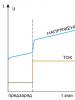
Let's tell you more about the operation of the multivibrator. After turning on the power, transistors VT1 and VT2 are closed, since there is zero potential at the base of transistor VT1. Capacitor C1 begins to charge through resistor R2 and a chain of series-connected elements R1.BF1. This process proceeds linearly until the voltage on capacitor C1 exceeds the opening threshold of transistor VT1.

As soon as transistor VT1 starts to open, VT2 also opens. At the “Exit” point positive voltage appears. Through resistor R1, it is added to the voltage on capacitor C1 and supplied to the base of transistor VT1. And that, in turn, opens even more, and opens VT2 even more. An avalanche-like process occurs, leading to the fact that transistors VT1 and VT2 enter saturation, and the full battery voltage is applied to the telephone capsule BF1 through the open transistor VT2.
This state is unstable and will continue while capacitor C1 is recharged through resistor R1. Once the capacitor is recharged, it will not be able to provide sufficient base current to transistor VT1 to maintain saturation mode. VT1 will begin to close, closing VT2 as well. Positive voltage at the “Output” point will decrease, thereby reducing the voltage at the base of VT1 - it closes even more, dragging VT2 with it.
An avalanche-like process occurs again, as a result of which the transistors are completely closed. The base of VT1 is under negative voltage provided by capacitor C1, which acquired it during the recharging process. This voltage is not kept constant, but due to the current through resistor R2 it smoothly goes to zero and then, reaching a positive value sufficient to open VT1, causes a new cycle.
Thus, the multivibrator periodically connects the telephone capsule to the battery, allowing sound to be emitted. It should be noted that the current consumed from the battery is also modulated by the frequency of the generator, and if a second telephone capsule is connected in series with the battery, it will also emit sound.
O. Khovaiko, Moscow.
The circuit diagram of the PU is shown in Fig. 2. The amplifier is assembled on an operational amplifier (op-amp). This is a medium precision op-amp with built-in correction and output protection against short circuit in the load.
Let's consider the operation of the amplifier. The signal from the carbon microphone VM1 with an amplitude of 30...60 mV is amplified by the op-amp to a voltage of 1 V. The op-amp gain is set by resistors R5 and R4 and is selected equal to 20...30 (Ku=R5/R4=240k/9.1k=26, 3).
These values of the gain of a given op-amp and the amplitude of the input signal from the microphone were obtained from experimental data and are optimal. The longest communication range is ensured by the maximum amplitude of the signal in the line, at which there is no distortion. When a signal with an amplitude of 150 mV was applied to the input of the amplifier, a signal with an amplitude of 3.5 V was obtained at the output of the control unit. As the input signal increased further, noticeable distortion began. Increasing the op-amp gain more than 30 is impractical, because the probability of self-excitation of the amplifier increases.
The input signal level is set by resistor R1, which determines the current passing through the carbon microphone. A decrease in resistance causes an increase in current through the carbon microphone, which means an increase in the input voltage taken from the microphone and supplied to the op-amp.
If an MKE-3 electret microphone or an electrodynamic DEMSh microphone is used, then resistor R1 can be eliminated and the switching circuit for the microphone used can be used.
A voltage divider consisting of resistors R2 and R3 allows for unipolar power supply. These resistors should, if possible, be of the same value, otherwise signal distortion at the output of the op-amp cannot be ruled out. Their choice will be correct if the voltage measured at pin 6 of the op-amp is equal to half the supply voltage.
Resistor R6 is balanced, necessary to ensure duplex communication. It performs the function of a resistor Ra or Rb (Fig. 1).
Resistor R7 allows you to adjust to different line resistances and the resistance of the telephone capsule, and therefore eliminate the local effect when the signal from your microphone drowns out the signal coming to your phone from the interlocutor. If there are several lines and subscribers, it makes sense to make resistor R7 variable and bring it out for operational adjustment on the case.
To call another subscriber, just press the S1 “Call” button. In this case, the feedback formed by capacitor C2 turns the op-amp into an RC oscillator. The amplitude of the signal in the line during a call is from 3.5 to 4.5 V, the repetition rate of rectangular pulses is 1 kHz. The power released in the telephone capsule of the interlocutor is at least 150 mW. This is enough to hear the call.
Rice. 2
A little about the design and details of the PU. The printed circuit board (Fig. 3) for the amplifier is made of single-sided foil-coated fiberglass 1.5 mm thick.
SP3-1b is used as a tuning resistor R7 in the amplifier; it can be replaced with SP-4 or a variable resistor, for example, SP3-41. All other resistors are MLT-0.125 W. Oxide capacitor C1 - K56-12 (or K50-35); . C3 - K50-35; capacitor C2 - MBM. Instead of a microcircuit, one made in a rectangular plastic case is suitable. Switch S1 - PKN2-1V, switch S2 - P2K. Telephone capsule - resistance 50...60 Ohm, microphone - carbon, electrodynamic (DEMS), electret (MKE-3). Power source - battery "Krona", "Korund", "Nika".
Now about the setup. The first thing to do is to check that the pins of the DA1 microcircuit are correctly soldered (if you look at it from the side of the legs, then opposite the key-metal protrusion there will be the first leg of the microcircuit and then clockwise - the second, third, etc.). If you are not satisfied with the quality of the connection, you will have to deal with the control panel more thoroughly. You will need an audio frequency generator, an oscilloscope and an avometer. Then we can recommend the following algorithm of actions. Check whether there is a voltage at pin 6 of the microcircuit equal to half the supply voltage. If necessary, set the desired mode by more accurately selecting resistors R2 and R3.
Having connected the oscilloscope first to the microphone and then to the PU output, measure the signal amplitude in each case while talking in front of the microphone. If the signal from the microphone is significantly less than 50 mV, change the microphone. If there are no other microphones at hand, and the signal from this one no longer develops with any selection of R1, try increasing the gain of the op-amp by increasing the resistance of resistor R5 or decreasing R4.
When observing a signal from a microphone using an oscilloscope, many harmonics of different frequencies and amplitudes are visible; it is difficult to determine and measure the true amplitude of the signal. Therefore, it is better to temporarily turn off the microphone and instead apply a sinusoidal signal with a frequency of 1000 Hz from the generator. Using an oscilloscope, measure the signal amplitude at the input (pin C1, left in the diagram) and output (pin 6 of the op-amp) of the amplifier, determine the gain and, if it turns out to be less than 20, select resistors R4 and R5.