DIY powerful current pulse generator. Pulse generators. Output parameters
Pulse generators are an important component of many radio-electronic devices. The simplest pulse generator (multivibrator) can be obtained from a two-stage ULF (Fig. 6.1). To do this, simply connect the amplifier's input to its output. The operating frequency of such a generator is determined by the values of R1C1, R3C2 and the supply voltage. In Fig. 6.2, 6.3 show multivibrator circuits obtained by simply rearranging the elements (parts) of the circuit shown in Fig. 6.1. It follows that the same simple diagram can be depicted in different ways.

Practical examples of using a multivibrator are shown in Fig. 6.4, 6.5.
In Fig. Figure 6.4 shows a generator circuit that allows you to smoothly redistribute the duration or brightness of the LEDs connected as a load in the collector circuit. By rotating the R3 potentiometer knob, you can control the ratio of the durations of the LEDs of the left and right branches. If you increase the capacitance of capacitors C1 and C2, the generation frequency will decrease and the LEDs will begin to blink. As the capacitance of these capacitors decreases, the generation frequency increases, the flickering of the LEDs will merge into a continuous glow, the brightness of which will depend on the position of the potentiometer R3 knob. Based on such a circuit design, various useful structures can be assembled, for example, a brightness control for an LED flashlight; toy with blinking eyes; a device for smoothly changing the spectral composition of the radiation source (multi-colored LEDs or miniature light bulbs and a light-summing screen).


The variable frequency generator (Fig. 6.5) designed by V. Tsibulsky allows you to obtain sound that smoothly changes over time in frequency [R 5/85-54]. When the generator is turned on, its frequency increases from 300 to 3000 Hz in 6 seconds (with a capacitor capacity of SZ 500 μF). Changing the capacitance of this capacitor in one direction or another accelerates or, conversely, slows down the rate of change in frequency. You can smoothly change this speed with variable resistance R6. In order for this generator to act as a siren, or to be used as a sweeping frequency generator, it is possible to provide a circuit for forced periodic discharge of the SZ capacitor. Such experiments can be recommended for independent expansion of knowledge in the field of pulse technology.


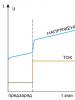
A controlled square pulse generator is shown in Fig. 6.6 [R 10/76-60]. The generator is also a two-stage amplifier covered by positive feedback. To simplify the generator circuit, it is enough to connect the emitters of the transistors with a capacitor. The capacitance of this capacitor determines the operating frequency of generation. In this circuit, a varicap is used as a voltage-controlled capacitance to control the generation frequency. An increase in the blocking voltage on the varicap leads to a decrease in its capacity. Accordingly, as shown in Fig. 6.7, the operating frequency of generation increases.

The varicap, as an experiment and to study the operating principle of this semiconductor device, can be replaced with a simple diode. It should be taken into account that germanium point diodes (for example, D9) have a very small initial capacitance (of the order of several pF), and, accordingly, provide a small change in this capacitance depending on the applied voltage. Silicon diodes, especially power diodes designed for high current, as well as zener diodes, have an initial capacity of 100... 1000 pF, so they can often be used instead of varicaps. Pn junctions of transistors can also be used as varicaps, see also Chapter 2.
To control the operation, the signal from the generator (Fig. 6.6) can be applied to the input of the frequency meter and the tuning limits of the generator can be checked when the control voltage changes, as well as when changing a varicap or its analogue. It is recommended that the results obtained (control voltage values and generation frequency) when using different types of varicaps be entered into a table and displayed on a graph (see, for example, Fig. 6.7). Note that the stability of generators based on RC elements is low.


In Fig. 6.8, 6.9 show typical circuits of light and sound pulse generators made on transistors of various conductivity types. Generators are operational in a wide range of supply voltages. The first of them produces short flashes of light with a frequency of one Hz, the second produces pulses of sound frequency. Accordingly, the first generator can be used as a beacon, a light metronome, the second - as a sound generator, the oscillation frequency of which depends on the position of the potentiometer R1. These generators can be combined into a single unit. To do this, it is enough to turn on one of the generators as a load of the other, or in parallel with it. For example, instead of a chain of LEDs HL1, R2 or in parallel with it (Fig. 6.8), you can turn on the generator according to the circuit in Fig. 6.9. The result will be a periodic sound or light and sound signaling device.
The pulse generator (Fig. 6.10), made on a composite transistor (p-p-p and p-p-p), does not contain capacitors (a piezoceramic emitter BF1 is used as a frequency-setting capacitor). The generator operates at a voltage from 1 to 10 B and consumes a current from 0.4 to 5 mA. To increase the sound volume of a piezoceramic emitter, it is tuned to the resonant frequency by selecting resistor R1.


In Fig. Figure 6.11 shows a rather original generator of relaxation oscillations, made on a bipolar avalanche transistor.
The generator contains as an active element a transistor of the K101KT1A microcircuit with inverse switching in the mode with a “broken” base. The avalanche transistor can be replaced with its analogue (see Fig. 2.1).
Devices (Fig. 6.11) are often used to convert the measured parameter (light intensity, temperature, pressure, humidity, etc.) into frequency using resistive or capacitive sensors.
When the generator is operating, a capacitor connected in parallel to the active element is charged from the power source through a resistor. When the voltage on the capacitor reaches the breakdown voltage of the active element (avalanche transistor, dinistor, or similar element), the capacitor is discharged into the load resistance, after which the process is repeated with a frequency determined by the constant of the RC circuit. Resistor R1 limits the maximum current through the transistor, preventing its thermal breakdown. The timing circuit of the generator (R1C1) determines the operating range of generation frequencies. Headphones are used as an indicator of sound vibrations for quality control of generator operation. To quantify the frequency, a frequency meter or pulse counter can be connected to the generator output.
The device is operational in a wide range of parameters: R1 from 10 to 100 kOhm (and even up to 10 MOhm), C1 - from 100 pF to 1000 μF, supply voltage from 8 to 300 V. The current consumed by the device usually does not exceed one mA. It is possible for the generator to operate in standby mode: when the base of the transistor is shorted to ground (common bus), generation is interrupted. The converter-generator (Fig. 6.11) can also be used in the mode of a touch key, a simple Rx and Cx meter, a tunable wide-range pulse generator, etc.
Pulse generators (Fig. 6.12, 6.13) are also made on avalanche transistors of the K101KT1 microcircuit of the p-p-p type or K162KT1 of the p-p-p type, dinistors, or their analogues (see Fig. 2.1). The generators operate at a supply voltage above 9 B and produce a triangular voltage. The output signal is taken from one of the terminals of the capacitor. The input resistance of the cascade following the generator (load resistance) must be tens of times greater than the value of resistance R1 (or R2). A low-resistance load (up to 1 kOhm) can be connected to the collector circuit of one of the generator transistors.


Quite simple and often encountered in practice pulse generators (blocking generators) using inductive feedback are shown in Fig. 6.14 [A. With. USSR 728214], 6.15 and 6.16. Such generators are usually operational over a wide range of supply voltage changes. When assembling blocking generators, it is necessary to observe the phasing of the terminals: if the “polarity” of the winding is connected incorrectly, the generator will not work.


Such generators can be used when testing transformers for the presence of interturn short circuits (see Chapter 32): such defects cannot be detected by any other method.
Literature: Shustov M.A. Practical circuit design (Book 1), 2003
The pulse current generator (PGG) is designed for the primary conversion of electrical energy. Includes an AC electrical network with a frequency of 50 Hz, a high-voltage transformer, a rectifier, a current-limiting device, and protection equipment. In the GIT, charging and discharging circuits are distinguished, which are interconnected by a bank of capacitors. The GIT, which is a power source, is connected to the technological unit through a discharge circuit.
Pulse generators are characterized by the following main parameters: voltage across the capacitor bank U, electric capacity of the battery C, energy accumulated in capacitors W n, energy in impulse W 0 pulse repetition frequency υ.
The purpose of the charging circuit is to charge a bank of capacitors to a given voltage. The circuit includes a current-limiting device, a step-up transformer and a high-voltage rectifier. Selenium or silicon pillars are used to rectify the charging current. Using a high-voltage transformer, the initial voltage of the 380/220 V supply network is increased to (2-70) 10 3 V.
In the diagram L - C – D we have ή 3 > 50%.
When using pulsed current generators, energy losses are significant at the stage of discharge formation. The common system that combines pulse current and voltage generators does not have this drawback (Fig. 30). In this system, the breakdown of the forming gap is produced by the energy of the capacitor bank of the voltage generator, which creates a current-carrying channel in the main working gap and ensures the release of the main discharge energy in the discharge gap of the pulse current generator.
The characteristic ratio of electrical voltages and capacitances for such a system is: » where index 1 corresponds to the voltage generator, and index 2 to the current generator. So, for example
The energy and weight-size parameters of the generator significantly depend on the high-voltage transformer and rectifier. The efficiency of the charging-rectifying device increases when using high-voltage silicon pillars. Rectifiers have high characteristic values - specific


volume from 0.03 to 0.28 m 3 /kW and specific gravity 25-151 kg/kW.
In electric pulse installations, single units are also used, including a transformer and a rectifier, which reduces the main dimensions and simplifies the switching network.
Pulse capacitors are designed to store electrical energy. High-voltage pulse capacitors must have increased specific energy capacity, low internal inductance and low resistance at high discharge currents, and the ability to withstand multiple charge-discharge cycles. The main technical data of pulse capacitors are given below.
Voltage (nominal), kV................................5-50
Capacitance (nominal), µF. . ....................................0.5-800
Discharge frequency, number of pulses/min.................................1-780
Discharge current, kA................................................... .............0.5-300
Energy intensity, J/kg.................................................... .......4.3-30
Resource, number of pulses................................................... .10 e - 3 10 7
One of the main characteristics of pulse capacitors, which affects the size of the battery and the electric pulse installation as a whole, is the indicator of specific volumetric energy intensity
 (3.23)
Where E n- accumulated energy; V to- capacitor volume.
For existing capacitors ω s= 20 -g 70 kJ/m 3, which determines the increased dimensions of the storage devices. So the battery capacity for E n= 100 kJ is 1.5-5.0 m 3. In storage devices, capacitors are connected into batteries, which ensures the summation of their electrical capacity, which is equal to 100-8000 μF.
High-voltage switches are used to instantly release electrical energy accumulated in a capacitor bank in a process unit. High-voltage switches (discharge arresters) perform two functions: they disconnect the discharge circuit


from the storage device when charging it; instantly connect the drive to the load circuit.
Various design schemes of arresters and types of switches corresponding to these schemes are possible: air, vacuum, gas-filled, contact disc, ignitron and trigatron, with a solid dielectric.
The basic requirements for switches are as follows: withstand high-voltage operating voltage without breakdown, have low inductance and low resistance, and provide a given current pulse repetition rate.
In laboratory electric pulse installations, mainly air-type spark gaps are used, which provide switching of high energies over a long service life and have a relatively simple design (Fig. 31).
Dischargers of this type have a number of significant disadvantages that limit their use: the influence of the surface condition and the state of the atmospheric air (dust, humidity, pressure) on the stability of the reproduced pulse; nitrogen oxides are formed, which have an effect on humans; powerful high-frequency sound pressure is generated.
In industrial mobile installations, mechanical disc switches have become widespread (see Fig. 31, A). Dischargers of this type are simple in electrical circuit and design, reliable during transportation and operation in areas with rough terrain, but require regular cleaning of the surface of the disc elements. I
The electric pulse installation also includes control units for the pulse generator and the technological process, protection and interlock systems, and auxiliary systems that provide mechanization and automation of processes in the technological unit.
The control unit includes electrical circuits for starting, blocking and a synchronization pulse generation circuit.
The interlock system serves to “instantly shut off high voltage voltage. The control system consists of a voltmeter and a kipovoltmeter, indicating the mains voltage and the capacitor bank voltage, respectively, indicator lamps, sound signals, and a frequency meter.
Technological node
The technological unit is designed to convert electrical energy into other types of energy and to transfer the converted energy to the processing object.
In relation to the specifics of discharge-pulse technology for rock destruction, the technological unit includes: a working discharge chamber, a working element in the form of an electrode system or an electrohydraulic fuse, a device for inlet and outlet of working fluid and a device for moving electrodes or an exploding conductor (Fig. 32). The working discharge chamber is filled with a working liquid or a special dielectric compound.
Discharge (working) chambers are divided into open and closed, buried and surface, stationary, mixed and remote. Cameras can be disposable or reusable; vertical, horizontal and inclined. The type and shape of the working chamber must ensure maximum release of accumulated electrical energy, maximum hp. converting this energy into mechanical energy, transferring this energy to the processing object or to its specified zone.
The working technological element is designed to directly convert electrical energy into mechanical energy and to input this energy into the working environment, and through it to the processing object. The type of working element depends on the type of electrical discharge in the liquid used in a given technological process - with free formation of the discharge, electrode systems are rational (Fig. 33, A); with an initiated discharge - an electro-hydraulic fuse with an exploding conductor (Fig. 33.6).
The working body experiences dynamic loads, the action of an electromagnetic field and ultraviolet radiation, as well as the influence of the working fluid.


The electrode system is used with free discharge formation. According to the design factor, rod linear and coaxial systems are distinguished. The simplest in design are linear (opposing or parallel) systems with combinations of electrode shapes: tip - tip and tip - plane. The disadvantages of linear systems are their significant inductance (1-10 μH) and non-directional action.
Coaxial systems are more advanced, having low self-inductance and high efficiency. converting accumulated electrical energy into plasma energy. The disadvantage of coaxial systems is their low reliability and fragility. The electrode system is technologically advanced and highly productive due to the high frequency of the process of creating mechanical loading forces.
Based on the number of repeated discharges, single-acting and multiple-acting systems are distinguished. Reusable systems are more economical and productive. The amount of energy converted by the electrode system also affects design and durability.
In the mining industry, electrode systems designed for pulse repetition rates of 1-12 per minute have become more widely used. During an electrical discharge, due to thermal processes, erosion of the electrodes occurs, the intensity of which depends on the material of the electrodes and the working fluid, as well as on the amount of energy released in
discharge channel. The working part of the electrodes is made of steel St3 or St45; the diameter of the protruding part must be more than 8 mm with a length of at least 12 mm. In the electrode zone, the melting temperature of iron is reached in 10 -6 s, and the boiling point in 5 10 -6 s.
The resulting intense destruction of the electrode is accompanied by the formation of plasma jets (vapors and liquid drops of metal). The weakened zone of the electrode is the insulating layer at the boundary between the output of the rod - the current conductor and water.
The main requirements for the electrode system are: high electrical energy conversion coefficient, high
operational and technological indicators, economically feasible durability. Electrodes made of an alloy of copper, tungsten carbide and nickel have the greatest erosion resistance.
The surface area of the cathode should exceed the area of the anode by 60-100 times, which, combined with the application of a positive voltage pulse to the anode, will reduce energy losses at the stage of discharge formation and increase efficiency. systems. Rational insulation materials are fiberglass, vacuum rubber, polyethylene.
An electrohydraulic fuse is used in an initiated discharge; it absorbs dynamic loads, the effects of high-current fields and working fluid, which leads to the destruction of the housing, insulation and electrode.
In an electrohydraulic fuse, the positive electrode is isolated from the body; an exploding conductor is installed between the electrode and a grounded body, which acts as a negative electrode.
Depending on the technological problems being solved, conductors made of copper, aluminum, and tungsten are used; Conductor dimensions range from diameter 0.25-2 mm, length 60-300 mm. The design of the electrohydraulic fuse must ensure the concentration of energy in the required direction and the formation of a cylindrical shock wave front, as well as the manufacturability of operations for installing and replacing the exploding conductor.
To fulfill part of these requirements, it is necessary that the body of the electrohydraulic fuse serves as a rigid barrier for the propagating wave front.
This is ensured by the use of special cumulative recesses in the fuse body and a certain combination of linear dimensions of the body and conductor. Thus, the diameter of the fuse body should be 60 times or more greater than the diameter of the exploding conductor.
In recent years, new design schemes and special devices have been developed that increase the efficiency of the working bodies, ensuring that the action is directed towards the processing object of the generated waves and hydraulic flow.
Such devices include passive reflective surfaces, electrodes with complex geometries, and divergent wave generators. There are also devices for drawing the exploding conductor, which complicates the design of the fuse, but increases the manufacturability of the process.
To directly convert the energy of an electric discharge into the energy of a compression pulse, special electric explosive cartridges are used (Fig. 34).
The working fluid filling the technological unit plays a very significant role in the process of electrical discharge. It is in the liquid that the discharge is reproduced with the direct conversion of electrical energy into mechanical energy.
Ionization is observed in the liquid, as well as gas release of unreacted oxygen and hydrogen (up to 0.5 10 -6 m 3 / kJ), the liquid is drawn into motion by the propagating wave front, which forms a hydraulic flow in the technological unit, capable of performing mechanical work.


Water (technical, sea, distilled) and aqueous electrolytes are used as the working fluid; hydrocarbon (kerosene, glycerin, transformer oil) and silicone (polymethylsiloxane) liquids, as well as special dielectric, liquid and solid compositions. Process water, whose specific electrical conductivity is (1-10) S/m, has become more widely used.
The electrical conductivity of the liquid significantly affects the amount of energy required to form a discharge, since it determines the magnitude of the breakdown voltage and the speed of movement of the streamers. The minimum voltage at which streamers appear is estimated at 3.6 10 3 V/mm.
The specific electrical conductivity values (S/m) of some liquids used to fill the technological unit are given below.
Process water (tap)................................................... ............(1-10) 10 -2
Sea water................................................ ........................................1-10
Distilled water................................................ ........................4.3 -10 -4
Glycerol................................................. ........................................................ ..6.4 10 -6
It can be seen that dielectric liquids have low ionic conductivity. The specific electrical resistance of the liquid (r l) also determines the value of the electrical efficiency. and depends on the amount of energy introduced per unit volume of working fluid. Thus, for water, the parameter rj decreases with increase to values of 500-1000 kJ/; with a further increase in W 0, the parameter rz stabilizes within the range of 10-25 Ohm-m.
The electric discharge in a liquid also depends on the density of the working liquid - with increasing density, the peak of overvoltages and the steepness of the current decline decrease. To increase the voltage of the discharge circuit, and, accordingly, the value of the breakdown voltage, working fluids with low specific conductivity (for example, industrial water) should be used.
The use of liquids with higher conductivity facilitates the formation of sliding discharges; increases energy losses at the stage of channel formation and reduces the amplitude of the shock wave.
Viscous compositions are also used as a working fluid (spindle oil - 70%, aluminum powder - 20%, chalk - 10%), which increases the amplitude of the shock wave by 20-25% and reduces energy losses.
Metallized dielectric thread and paper tapes impregnated with electrolyte are also used as a dielectric. The introduction of a solid dielectric reduces the total energy consumption for breakdown (4-5 times), reduces the required number of streamers (4-6 times), reduces thermal radiation and ultraviolet radiation. The introduction of solid particles of conductive additives into the flow of working fluid is used instead of exploding conductors.
The generator, depending on the voltage of the power source, produces high-voltage pulses with an amplitude of up to 25 kV. It can be powered by a 6V galvanic battery (four A-type cells), a 6...12V battery, a car's on-board power supply, or a laboratory power supply up to 15V. The range of applications is quite wide: electric fences on an animal farm, a gas lighter, an electroshock protective device, etc. In the manufacture of such devices, the greatest difficulties are caused by a high-voltage transformer.
Even if successfully manufactured, it is not reliable and often fails due to dampness or due to breakdown of the insulation between the coils. An attempt to make a high-voltage generator based on a diode voltage multiplier also does not always give a positive result.
The easiest way is to use a ready-made high-voltage transformer - an automobile ignition coil from a car with a classic ignition system. This transformer is highly reliable and can operate even in the most unfavorable field conditions. The ignition coil design is designed for tough operation in all weather conditions.
The schematic diagram of the generator is shown in the figure. An asymmetrical multivibrator is made on transistors VT1 and VT2; it produces pulses with a frequency of about 500 Hz. These pulses flow through the collector load of transistor VT2 - the primary winding of the ignition coil. As a result, an alternating pulse high-voltage voltage is induced in its secondary winding, which has a significantly larger number of turns.
This voltage is supplied to the spark gap, if it is a self-defense device or a gas lighter, or to an electric fence. In this case, voltage is supplied to the fence from the central terminal of the ignition coil (from the terminal from which voltage is supplied to the distributor and spark plugs), and the common plus of the circuit must be grounded.
If the generator will be used as a means of self-defense, it is most convenient to make it in the form of a stick. Take a plastic or metal tube of such a diameter that the ignition coil with its metal body is tightly inserted into it. In the remaining space of the pipe, place batteries and transistors. S1 in this case is the instrument button. The upper part of the reel body will have to be redone.
It is most convenient to take an old-style plug for a 220V network, with screw-out contacts. The hole for the wire in it must be drilled so that the part of the ignition coil with a high-voltage contact fits tightly into it. Then you need to remove the mounting wires from this contact and from the general plus of the circuit and, along the very edges of the plug, bring them to the pin contacts of the plug.
Then this plug must be coated with epoxy glue in the drilled hole for the wire and pressed tightly onto the plastic body of the high-voltage contact of the coil. You need to screw discharge petals under the pin contacts of the plug, the distance between which should be about 15 mm.
The ignition coil can be anything from a contact ignition system (not suitable for electronic ignition), preferably imported - it is smaller in size and operating.
The setting consists of selecting the value of R1 so that there is a reliable electrical discharge between the discharge petals.
Pulse generators are designed to produce pulses of a certain shape and duration. They are used in many circuits and devices. They are also used in measuring technology for setting up and repairing various digital devices. Rectangular pulses are great for testing the functionality of digital circuits, while triangular pulses can be useful for sweep or sweep generators.
The generator generates a single rectangular pulse by pressing a button. The circuit is assembled on logical elements based on a regular RS trigger, which also eliminates the possibility of bouncing pulses from the button contacts reaching the counter.

In the position of the button contacts, as shown in the diagram, a high level voltage will be present at the first output, and at the second output a low level or logical zero, when the button is pressed, the state of the trigger will change to the opposite. This generator is perfect for testing the operation of various meters

In this circuit, a single pulse is generated, the duration of which does not depend on the duration of the input pulse. Such a generator is used in a wide variety of options: to simulate input signals of digital devices, when testing the functionality of circuits based on digital microcircuits, the need to supply a certain number of pulses to some device under test with visual control of processes, etc.

As soon as the power supply to the circuit is turned on, capacitor C1 begins to charge and the relay is activated, opening the power supply circuit with its front contacts, but the relay will not turn off immediately, but with a delay, since the discharge current of capacitor C1 will flow through its winding. When the rear contacts of the relay are closed again, a new cycle will begin. The switching frequency of the electromagnetic relay depends on the capacitance of capacitor C1 and resistor R1.
You can use almost any relay, I took . Such a generator can be used, for example, to switch Christmas tree lights and other effects. The disadvantage of this scheme is the use of a large capacitor.
Another generator circuit based on a relay, with an operating principle similar to the previous circuit, but unlike it, the repetition frequency is 1 Hz with a lower capacitor capacitance. When the generator is turned on, capacitor C1 begins to charge, then the zener diode opens and relay K1 operates. The capacitor begins to discharge through the resistor and the composite transistor. After a short period of time, the relay turns off and a new generator cycle begins.

The pulse generator, in Figure A, uses three AND-NOT logic elements and a unipolar transistor VT1. Depending on the values of capacitor C1 and resistors R2 and R3, pulses with a frequency of 0.1 - up to 1 MHz are generated at output 8. Such a huge range is explained by the use of a field-effect transistor in the circuit, which made it possible to use megaohm resistors R2 and R3. Using them, you can also change the duty cycle of the pulses: resistor R2 sets the duration of the high level, and R3 sets the duration of the low level voltage.
VT1 can be taken from any of the KP302, KP303 series. - K155LA3.
If you use CMOS microcircuits, for example K561LN2, instead of K155LA3, you can make a wide-range pulse generator without using a field-effect transistor in the circuit. The circuit of this generator is shown in Figure B. To expand the number of generated frequencies, the capacitance of the timing circuit capacitor is selected by switch S1. The frequency range of this generator is 1 Hz to 10 kHz.

The last figure shows the circuit of the pulse generator, which includes the ability to adjust the duty cycle. For those who have forgotten, let us remind you. The duty cycle of pulses is the ratio of the repetition period (T) to the duration (t):

The duty cycle at the output of the circuit can be set from 1 to several thousand using resistor R1. The transistor operating in switching mode is designed to amplify power pulses

The generator circuit shown in the figure is capable of generating rectangular and sawtooth pulses. The master oscillator is made on logic elements DD 1.1-DD1.3 of the K561LN2 digital microcircuit. Resistor R2 paired with capacitor C2 form a differentiating circuit, which generates short pulses with a duration of 1 μs at the output of DD1.5. An adjustable current stabilizer is assembled on a field-effect transistor and resistor R4. Current flows from its output to charging capacitor C3 and the voltage across it increases linearly. When a short positive pulse arrives, transistor VT1 opens and capacitor SZ discharges. Thereby forming a sawtooth voltage on its plates. Using a variable resistor, you can regulate the capacitor charge current and the steepness of the sawtooth voltage pulse, as well as its amplitude.
Variant of an oscillator circuit using two operational amplifiersThe circuit is built using two LM741 type op-amps. The first op amp is used to generate a rectangular shape, and the second one generates a triangular shape. The generator circuit is constructed as follows:

In the first LM741, feedback (FE) is connected to the inverting input from the output of the amplifier, made using resistor R1 and capacitor C2, and feedback is also connected to the non-inverting input, but through a voltage divider based on resistors R2 and R5. The output of the first op-amp is directly connected to the inverting input of the second LM741 through resistance R4. This second op amp, together with R4 and C1, form an integrator circuit. Its non-inverting input is grounded. Supply voltages +Vcc and –Vee are supplied to both op-amps, as usual to the seventh and fourth pins.
The scheme works as follows. Suppose that initially there is +Vcc at the output of U1. Then capacitance C2 begins to charge through resistor R1. At a certain point in time, the voltage at C2 will exceed the level at the non-inverting input, which is calculated using the formula below:
V 1 = (R 2 / (R 2 +R 5)) × V o = (10 / 20) × V o = 0.5 × V o
The output of V 1 will become –Vee. So, the capacitor begins to discharge through resistor R1. When the voltage across the capacitance becomes less than the voltage determined by the formula, the output signal will again be + Vcc. Thus, the cycle is repeated, and due to this, rectangular pulses are generated with a time period determined by the RC circuit consisting of resistance R1 and capacitor C2. These rectangular shapes are also input signals to the integrator circuit, which converts them into a triangular shape. When the output of op amp U1 is +Vcc, capacitance C1 is charged to its maximum level and produces a positive, upward slope of the triangle at the output of op amp U2. And, accordingly, if there is –Vee at the output of the first op-amp, then a negative, downward slope will be formed. That is, we get a triangular wave at the output of the second op-amp.
The pulse generator in the first circuit is built on the TL494 microcircuit, perfect for setting up any electronic circuits. The peculiarity of this circuit is that the amplitude of the output pulses can be equal to the supply voltage of the circuit, and the microcircuit is capable of operating up to 41 V, because it is not for nothing that it can be found in power supplies of personal computers.

You can download the PCB layout from the link above.
The pulse repetition rate can be changed with switch S2 and variable resistor RV1; resistor RV2 is used to adjust the duty cycle. Switch SA1 is designed to change the operating modes of the generator from in-phase to anti-phase. Resistor R3 must cover the frequency range, and the duty cycle adjustment range is regulated by selecting R1, R2
Capacitors C1-4 from 1000 pF to 10 µF. Any high-frequency transistors KT972
A selection of circuits and designs of rectangular pulse generators. The amplitude of the generated signal in such generators is very stable and close to the supply voltage. But the shape of the oscillations is very far from sinusoidal - the signal is pulsed, and the duration of the pulses and pauses between them is easily adjustable. Pulses can easily be given the appearance of a meander when the duration of the pulse is equal to the duration of the pause between them
Generates powerful short single pulses that set a logical level opposite to the existing one at the input or output of any digital element. The pulse duration is chosen so as not to damage the element whose output is connected to the input under test. This makes it possible not to disrupt the electrical connection of the element under test with the rest.
Schema and theories of action
As shown in Fig. 3.2, the current-limiting transformer T1 is connected to the bridge rectifier D1-D4 and charges the external storage capacitor C through the overvoltage protection resistor R18. An external storage capacitor is connected between the discharge ground and the spark gap electrode G1. The load in this project is not connected as standard, but between the discharge ground and the spark gap electrode G2. Note that the load is complex, usually highly inductive (not in all cases) with little resistance from the Load inductor wire. The spark gap electrodes G1 and G2 are located at a distance 1.2-1.5 times greater than the breakdown distance at a given voltage.
The third trigger electrode TE1 is discharged by a short high-voltage pulse of low energy into G2, creating a voltage peak that ionizes
Rice. 3.2. Schematic diagram of a pulse generator
Note:
Special note regarding diodes D14, D15. The polarity can be reversed to produce a greater trigger effect with low impedance loads, as is the case with can warping devices, wire exploding devices, plasma weapons, etc.
Attention! If the load impedance is too high, energy can be directed back through the diodes and transformer T2 and cause these components to fail.
Note that the circuit ground and common wire are isolated from each other.
The discharge ground is connected to the chassis and ground through the green wire of the power cord.
To ensure greater safety, it is recommended to use non-latching buttons as the S3 switch, which is only activated when pressed.
If the device is located in a location where unauthorized personnel have access, it is recommended to use a key switch as S4.
a gap between G1 and G2, which leads to the discharge of the energy accumulated in the external capacitive storage device into a load with complex resistance.
The charge voltage of the external capacitive storage device is set by the resistive divider circuit R17, which also produces a signal for the voltmeter Ml. The charge voltage is set by a variable control resistor R8 connected in series with R17. This control signal sets the turn-off level of comparator II, which sets the DC bias of transistor Q1. In turn, Q1 controls the relay, which turns the relay off. The contacts of the de-energized relay RE1 remove the power supply to the primary winding T1. When R8 is set to a given value, it automatically maintains a certain voltage level in external capacitive storage devices. The S3 safety button provides the ability to manually delay the charge of the external capacitor.
The red LED LA1 lights up when the power is turned on. The yellow LED LA2 lights up when the charge reaches the set value.
The trigger electrode circuit is a special capacitive discharge (CD) system, where the energy of capacitor C6 is directed to the primary winding of pulse transformer T2. A sequence of positive high voltage pulses is generated on the secondary winding T2, which is supplied to capacitors C8 and C9 through decoupling diodes D14 and D15. These high voltage DC pulses cause ionization in the gaps by discharge through the trigger electrode TE1. At the input of this circuit there is a voltage doubler consisting of capacitors C4, C5 and diodes D8 and D9. Start switch S1 supplies energy to the circuit, causing the spark gap to immediately operate. The silicon triode thyristor SCR removes the charge from C6, the unlocking current to the SCR is supplied by the DIAC dinistor, the bias to which is set by the variable resistance R14 and the capacitor C7.
The 12 V step-down voltage transformer TZ powers the control circuit, which also includes relay RE1. If the system does not have 12 V, it can only be started by activating RE1 manually. The diode rectifier D10-D13 rectifies the 12 V AC voltage, which is then filtered by the capacitive filter C1. Resistor R5 decouples power for control through the zener diode Z3, Z4, which is necessary for stable operation of the comparator circuit. Power for energy storage comes from the 115 VAC mains, with fuse F1 activated, and the 115 VAC mains is turned on by switch S4.
Comment
In our lab at Information Unlimited, the energy storage equipment includes 10 racks of oil-filled capacitors. Each rack houses 50 32uF 4500V capacitors connected in parallel to achieve a total capacitance of 1600uF or about 13000J at 4000V per rack. All 10 racks connected in parallel provide 130,000 J. At these energy levels, it is very important to properly connect and assemble the system with the required location and thickness of wires to produce pulses with power of hundreds of megawatts. To protect personnel from dangerous voltage, explosion shields are installed around storage racks.
The charging time for one stand is about 10 minutes. With this charge, using 10 racks would be impractical because it would take almost 2 hours to charge them. We use a 10,000 V, 1 A current charging system that can charge all 10 racks of oil capacitors to store 130,000 J of energy in 1 min . This high voltage charger is available upon special order.
Device pre-assembly procedure
This section assumes that you are familiar with basic tools and have sufficient assembly experience. The pulse generator is assembled on a metal chassis 25.4 × 43.2 × 3.8 cm, made of galvanized iron 1.54 mm thick (22 gauge). It uses an RMS transformer with a current limit of 6500 V, 20 mA. It is necessary to follow the given drawing as accurately as possible. You can use a more powerful transformer, then you will have to change the size of the device. We propose to connect in parallel up to 4 previously used transformers; to get a charging current of 80 mA. A voltmeter and controls are installed on the front panel. It is recommended to replace S4 with a key switch if the device is located in an area where unauthorized personnel have access.
When assembling the device, follow the following sequence of actions:
1. If you purchased a kit, lay out and identify all components and structural parts.
2. Cut a board from the blank with a 0.25 cm grid perforation and dimensions of 15.9 x 10.8 cm (6.25 x 4.25 inches).

Rice. 3.3. Pulse generator circuit board
Note:
The dotted line shows the connections on the back of the board. Large black dots indicate holes in the board that are used to install components and connections between them.
3. Insert the elements as shown in the figure. 3.3, and solder them to the terminals of the elements, to those contact pads where it is necessary, as you move from the lower left edge to the right. The dotted line shows the wire connections on the back of the board according to the circuit diagram. Avoid wire bridges, potential shorts and cold soldering as these will inevitably cause problems. Solder joints should be shiny and smooth, but not spherical.
4. Connect the circuit board with wires to the following points (see Fig. 3.3):
– to chassis ground with #18 vinyl-insulated wire, 20 cm long;
– with TE1 high voltage wire 20 kV, 10 cm long;
– with resistor R18, vinyl insulated wire #18 20 cm long;
– with anodes D3 and D4 with vinyl insulated wire #18 30 cm long (circuit ground);
– with TZ (2) 12 V DC with #22 vinyl insulated wire, 20 cm long;
– with a voltmeter M1 (2) with a #22 vinyl insulated wire 20 cm long. Check all connections, components, the location of all diodes, semiconductor elements, electrolytic capacitors CI, C2, C4, C5, C7. Check the quality of soldering, potential short circuits, and the presence of cold solder joints. Solder joints should be smooth and shiny, but not spherical. Check this carefully before turning on the device.
5. The spark gap is assembled as follows (Fig. 3.4):
– make the base BASE1 from a sheet of galvanized iron 1.4 mm thick (20 gauge) and dimensions 11.4 x 5 cm (4.75 x 2 inches);
– Make two BRKT1 brackets from 1.4 mm thick (20 gauge) galvanized iron sheet, each measuring 6.4 x 3.2 cm (2.5 x 1.25 in.). Fold the edge into a 1.9 cm visor;
– Make two BLK1 blocks from polyvinyl chloride (PVC) or similar material, 1.9 cm thick and 2.5 x 3.2 cm (1 x 1.25 in.) in size. They must have good insulating properties;
– make a BLK2 block from Teflon. It must withstand the high voltage trigger pulse;
– carefully solder the COL1 flanges to the BRK1 brackets. Adjust the fittings to ensure precise alignment of the tungsten electrodes after assembling the unit. At this point you will have to use a propane gas blowtorch, etc.;
– grind off the sharp ends of the eight screws. This is necessary to prevent the PVC material from breaking due to corona discharge generated at the sharp ends at high voltage;
– pre-assemble the parts, drill the necessary holes in them for assembly. Follow the picture for correct placement;

Rice. 3.4. Spark gap and ignition device
Note:
The spark gap is the heart of the system, and it is there that the energy accumulated by the capacitors over the entire charge period is quickly released into the load in the form of a high-power pulse. It is very important that all connections are able to withstand high currents and high discharge voltages.
The device shown here is designed for the HEP90 and is capable of switching at up to 3000 J of energy (when pulsed correctly), which is usually sufficient for efficient experimentation with mass transfer devices, can bending, wire exploding, magnetism and other similar projects.
A high energy switch capable of operating at 20,000J of energy can be supplied upon special order. Both switches use a high voltage trigger pulse that is dependent on the high line load impedance. This is usually not a problem for moderately inductive loads, but can become a problem for low inductance loads. This problem can be solved by placing some ferrite or ring cores in these lines. The cores react very strongly to the triggering pulse, but during the main discharge they reach saturation.
The design of the spark gap must take into account the mechanical forces that arise as a result of the action of strong magnetic fields. This is very important when working with physical energy and will require additional means to reduce inductance and resistance.
Attention! When conducting experiments, a screen must be installed around the device to protect the operator from possible fragments if the device breaks down.
For reliable starting, the starting gap must be set depending on the charge voltage. The gap should be located at least 0.6 cm from the bracket. If the switching is unstable, you need to experiment with this value.
– attach the large block lugs LUG1 to each side of the BRKT1 brackets. The connection must be made carefully, since the pulse current reaches kiloamperes;
– temporarily set the main gap to 0.16 cm and the trigger gap to 0.32 cm.
Procedure for final assembly of the device
The following are the final assembly steps:
1. Make the chassis and panel as shown in Fig. 3.5. It would be wise to make a square hole in the panel to accommodate a voltmeter before making the panel. The voltmeter that is used requires a 10 cm square hole. Other, smaller holes can be determined from the drawing and drilled after connecting the chassis and panel.

Note:
Make a front panel from 1.54 cm (22 gauge) galvanized iron sheet measuring 53.34 x 21.59 cm (21 x 8.5 in). Bend 5 cm on each side to connect to the chassis, as shown in the figure. Make a hole for the voltmeter.
Make a chassis from 1.54 cm (22 gauge) galvanized iron measuring 55.88 x 27.9 cm (22 x 15 in.). Fold 5 cm on each side and make a 1.25 cm canopy. The overall size will be (25x43x5cm) with a 1.25 cm canopy along the bottom of the chassis.
Make smaller holes and holes for connections as you proceed.
The visor going to the attached part of the chassis is not shown in the figure.
Rice. 3.5. Drawing for making the chassis
2. Try on the control panel and drill the necessary holes for controls, indicators, etc. Pay attention to the insulating material between the chassis and parts of the device, see fig. 3.6 part PLATE1. This can be achieved by using a small amount of RTV room temperature silicone adhesive sealant. Drill the appropriate holes as you work, checking for correct placement and dimensions.

Rice. 3.6. General view of the assembled device
Note:
Wires are shown slightly elongated to ensure clarity of images and connections.
The dotted lines show the components and connections located under the chassis.
3. Try on the remaining parts (see Fig. 3.6) and drill all the holes necessary for installation and placement. Pay attention to the fuse holders FH1 /FS1 and the insulation of the input power cord BU2. They are located on the underside of the chassis and are shown with dotted lines.
4. Provide sufficient space for high voltage components: transformer output terminals, high voltage diodes and resistor R18. Please note that the high voltage diodes are installed on the plastic board using double-sided RTV tape.
5. Reinstall the control panel. Secure the circuit board with a few pieces of tape coated with RTV adhesive once you are sure everything is fine.
6. Make all connections. Please note the use of wire nuts when connecting terminals T1 and T2.
Preliminary electrical tests
To perform preliminary electrical tests, follow these steps:
1. Short-circuit the output terminals of the transformer using a high-voltage wire with a clamp.
2. Remove the fuse and install a 60 W barretor in the fuse holder as a ballast for the testing period.
3. Set switch S4 (see Fig. 3.7) to the off state, move the axis of the switch combined with variable resistance R8/S2 to the “off” position, set variable resistances R14 and R19 to the middle position and turn on the device to a 115 V AC network by plugging the COl power cord into the electrical outlet.
4. Turn the axis of the combined switch with variable resistance R8 until it turns on and watch the lamps LA1 and LA2 light up.
5. Press the charge button S3 and make sure that the RE1 relay is turned on (a clicking sound is heard) and the LA2 lamp is extinguished while the S3 button is pressed.
6. Turn on S4 and press S3, notice that the barreter, turned on in accordance with point 2, burns at full heat.
7. Press the "Start" button S1 and observe the flash between the trigger electrode TE1 and the main discharge gap between G1 and G2. Please pay

Rice. 3.7. Front panel and controls
Please note that the variable resistance axis is set to the average value, but by turning the axis clockwise you can increase the discharge.
Basic tests
To carry out the tests, follow these steps:
1. Unplug the power cord and turn off S2 and S4.
2. Connect a 30uF, 4kV capacitor and a 5kOhm, 50W resistor as C and R as shown in Fig. 3.6.
3. Remove the ballast lamp and insert a 2A fuse.
4. Set the pilot gap to 0.32 cm and the main gap to 0.16 cm.
5. Connect a high-precision voltmeter through an external capacitor.
6. Turn on the device and turn on S2 and S4. Press button S3 and ensure that the external capacitor is charged to 1 kV before RE1 turns off. Note that in normal condition LA2 is on and off only for the duration of the charge cycle. When the set charge is reached, the LA2 LED turns on again, indicating that the system is ready.
7. Turn R8/S2 30° clockwise and notice that the voltage reaches a higher value before charging stops.
8. Press button S1 and observe the instantaneous powerful arc in the main gap that occurs when energy is directed to the external load.
9. Charge the device to 2500 V, measuring the voltage using an external voltmeter connected through a capacitor. Adjust R19 so that the front panel voltmeter reads 2.5 at full scale 5. Make a mark on the front panel so you know where the voltage is 2500 V. The front panel meter now reads the charge voltage with reasonable accuracy when the external voltmeter. Repeat step 8, observing a strong arc as the discharge occurs. Repeat charge and discharge cycles at different voltages to become familiar with the operation of the device.
This completes the verification and calibration of the device. Further operations will require additional equipment, depending on the project in which you are experimenting.
Useful mathematical relationships for bottom equipment
System storage energy:
The ideal current rise is achieved in LC systems. Use a factor of 0.75 when using oil capacitors and lower values for photo- and electrolytic capacitors. Time to reach peak current at 1 A cycle:
Magnetic flux

A = area of the coil face in m2; Le = distance between poles in m; M = mass in kg. Force:
![]()
Acceleration: Speed:
where t is the time to reach the peak current.