Nickel-cadmium batteries: device, restoration. How to charge a nickel-cadmium battery? What you need to know about nickel-cadmium batteries Zu for nickel-cadmium batteries
The charger is intended for charging nickel-cadmium (NiCd) and nickel-metal hydride (NiMH) batteries of AA and AAA sizes. It does not claim originality or novelty. The charger circuit is simple and reliable. During operation for more than 10 years there were no operational failures. There are no regulating elements in the circuit; the charging current is set automatically. The charger allows you to charge both one battery and a battery of several batteries. In this case, the charging current changes slightly.
A special feature of the system is its galvanic connection to a 220 V electrical network, which requires compliance with electrical safety measures. Diodes KD 105 or the like are used as diodes D1 - D7. LED D8 - AL307 or similar, the desired color of the glow. Diodes D1 - D4 can be replaced with a KTs405A diode assembly. Resistor R3 can be used to select the required brightness of the LED.
Capacitor C1 sets the required charging current. The capacitance of the capacitor is calculated using the following empirical formula:
V = (220 - Uemf) / J
where: C1 in uF; Uemf - battery voltage in V; J is the required charging current in A.
Example - it is necessary to calculate the capacitor capacity to charge a battery of 8 nickel-cadmium batteries with a capacity of 700 mAh. The charging current (J) will be 0.1 of the battery capacity - 0.07 A. Uemf 1.2 x 8 = 9.6 V. Therefore, B = (220 - 9.6) / 0.07 = 3005.7. Further A = 3005.7 - 200 = 2805.7. The capacitor capacity will be C1 = 3128 / 2805.7 = 1.115 µF. The closest nominal value is accepted - 1 µF.
The operating voltage of the capacitor must be at least 400 V. The capacitor must only be made of paper; the use of electrolytic capacitors is not allowed.
The power dissipation of resistor R2 is determined by the magnitude of the charging current. For a charging current of 0.07 A it will be 0.98 W (P= JxJxR). A resistor with a power dissipation of 2 W is selected.
A capacitor can be composed of several capacitors in parallel, series or mixed circuits.
The charger is not afraid of short circuits. After assembling the charger, you can check the charging current by connecting an ammeter instead of the battery.
Before connecting the charger to the electrical network, you must connect the battery to it. If the battery is connected in reverse polarity, LED D8 will light (before connecting the charger to the electrical network). When the battery is correctly connected and the charger is connected to the electrical network, the LED indicates the passage of charging current through the battery.
Download: Charger for NiCd and NiMH batteries
If you find broken links, you can leave a comment, and the links will be restored as soon as possible.
When using nickel-cadmium batteries, before charging them, they must be discharged to a voltage of 0.8 - 1 V per cell. At first I used a simple method - I loaded it with an incandescent lamp or a one-watt resistor, but there were cases when I forgot about the battery and it discharged to zero.
A simple device was made to discharge nickel-cadmium batteries.

The discharge current is set by the resistance of resistor R6, and for a battery with a voltage of 3.7 V and a capacity of 700 mAh, this is approximately 70 mA. The voltage threshold to which the battery is discharged is set by resistor R2. The discharge process is indicated by the HL1 LED. When the specified voltage is reached, transistor VT1 closes, reducing the discharge current to 3 - 5 mA, and the HL1 LED goes out. To set the threshold, you need to connect the device to the power supply and move the resistor R2 to a position at which the HL1 LED goes out.
Transistor VT1 - low-power, germanium, zener diode VD1 for stabilization voltage 2 - 3.3 V, for example KS130, KS133, KS433.
The converter operates from 3 to 1.8 V, while consuming 150 mA. Below 1.8 V (0.9 V for each battery), generation stops, the current drops to 10 - 15 mA and depends on the resistance of resistor R1, LEDs HL1 and HL2 go out, well, that’s all, you can charge the batteries.
If you need to discharge one battery, then a germanium diode VD1 should be used, for example D9, D18.
Transistor VT1 is silicon, with a collector-emitter saturation voltage of 0.5 - 0.8 V and with a constant collector current of at least 1 A, for example KT815, KT817, KT630, KT831.
Transformer T1 is wound on a ferrite ring with an outer diameter of 10 mm with a permeability of 1000 - 2000, contains two windings - 30 turns in the base circuit and 50 turns in the collector circuit, with a wire with a diameter of 0.15 mm. If the converter does not work when you first turn it on, you need to swap the terminals of one of the windings of transformer T1.
This time we will talk about designing a simple USB charger for Ni-Cd and Ni-Mh batteries.
The circuit of a fairly good charger is simple and can be implemented with a budget of only 20 rubles. This is already cheaper than any Chinese charger. The heart of our charger is the well-known LM317 linear stabilizer chip.

The input of the circuit is supplied with a voltage of 5 V from any USB port.

The microcircuit stabilizes the voltage to 1.5 V. This is the voltage of a fully charged Ni-Mh battery.
And the device works very simply. The battery will be charged with a voltage of 1.5-1.6 Volts from the microcircuit. Resistor R1, as a current sensor, simultaneously limits the charging current. By selecting it, the current can be reduced or increased.
When a battery is connected to the output of the circuit, a voltage drop is formed across resistor R1. It is enough to trigger a transistor, the collector circuit of which has an LED connected to it. The latter lights up and as the battery charges, it will go out until it turns off completely. This will happen at the end of the charging process.
Thus, the diode lights up when the battery is charging and goes out when the latter is fully charged. At the same time, as the battery charges, the current will decrease, and at the end its value will be 0.
It follows from this that overcharging and failure of the battery is impossible.
The LM317 chip operates in linear mode, so a small heat sink will not hurt. Although at a current of 300 mA the heating of the microcircuit is within normal limits. It is advisable to select an LED with a minimum operating voltage. Color is absolutely not important. Instead of BC337, it is allowed to use any low-power reverse conduction transistor, even on KT315. The desired power of resistor R1 is 0.5-1 Watt. All remaining resistors are 0.25 and even 0.125 Watts. Since the voltage range is very narrow, even resistor errors can affect the operation of the circuit. Therefore, it is strongly recommended to replace resistor R2 with a multi-turn resistor of 100 Ohms.
With its help, you can very accurately adjust the desired output voltage.
First you need to find all the necessary components, as well as a slot for batteries.
The device can charge batteries of almost any standard if you adapt the appropriate slot. When assembling, you do not need to use a printed circuit board. Installation is done using a hinged method. The components are glued under the battery slot and filled with hot glue, since the circuit is very reliable in operation.

The assembled device looks something like this:

But it can look much better.
You just need to select an LED with the lowest possible glow voltage, otherwise it may not light up at all. This scheme can charge several batteries, but it is recommended to use it only to charge one.


Ni─Cd batteries are widely used in various electronic devices and portable tools. For example, these are music players, cameras, and so on. In recent years, lithium-ion batteries have practically been replaced. Where previously nickel-cadmium batteries were used (laptops, mobile gadgets), lithium-type batteries now work. They could not replace them only in devices that require high discharge current (power tools). Cadmium batteries are quite demanding in terms of maintenance. You need to be able to use them correctly, charge them, and also do periodic charge-discharge cycles to eliminate the “memory effect.” In this case, Ni─Cd batteries will last a long time. In this material we will talk about how to charge nickel-cadmium batteries and about chargers for them.
How to charge Ni─Cd batteries?
In order to charge nickel-cadmium batteries, a special charger is required. There is a huge variety of such devices on the market. Among them, it is worth highlighting 2 main types of devices:
- automatic;
- reverse pulse.
Automatic chargers for nickel-cadmium batteries are simple devices. Their cost is low and their design is simple. They can simultaneously charge 2 or 4 batteries. To charge a Ni─Cd battery, it is simply inserted into the charger, the number of elements is selected and connected to the network. Many users of portable players and cameras know how to charge Ni─Cd batteries using automatic network chargers.
Reverse pulse chargers have a more complex design and are more expensive than automatic ones. Some manufacturers of such devices classify them as professional grade. Such chargers charge batteries cyclically at different time intervals. At the same time, many of them discharge and balance Ni─Cd batteries.
How to charge and discharge Ni─Cd batteries?
Discharging process
This type of battery has discharge characteristics that significantly depend on the battery parameters, which determine the value of internal resistance. For example, this is the thickness of the electrodes, their structure, etc. Below is a complete list of parameters that affect discharge characteristics:
- volume of electrolyte;
- thickness and structure of the separator material;
- assembly density;
- design features.
The highest capacity of a Ni-Cd battery is observed at 20 C. If the temperature rises, the capacity does not decrease. A value of 20 C is best for charging the battery.

If the ambient temperature drops into the negative region, then the value of the discharge capacity decreases in proportion to the increase in the discharge current. This is due to the fact that when the temperature decreases, the internal resistance of the battery increases and the discharge voltage decreases.
Charging Ni─Cd batteries
An important task when charging Ni─Cd batteries is to avoid overcharging. This is a very important point. When you charge a nickel-cadmium battery, the pressure inside it increases. During the charging process, oxygen is released and the charging current utilization rate decreases.

To fully charge a Ni─Cd battery, it needs to transfer up to 160% of its nominal capacity during charging. It is allowed to charge the battery in the range from 0 to 40 C, and it is advisable to do this from 10 to 30 C. If the temperature at the negative electrode drops, the absorption of oxygen decreases. At the same time, pressure begins to rise. If there is a significant overcharge, the emergency valve may be triggered by excess pressure. As the temperature rises, the battery's potential increases. In this case, oxygen begins to be released very early on the positive electrode.
To fully utilize the power of a Ni─Cd battery, you need to charge it with high charging currents. If you want to give it maximum capacity, then the charging current should be small (0.1*C). It will charge in this mode for approximately 14-16 hours. By applying current in stages, you can speed up the charging process of a Ni─Cd battery. According to this scheme, you need to charge with a current of 1 * C to 10% of the capacity, then 1.5 * C to 80 percent. The remaining capacity is filled with a current of 0.5*C.
Eventually
When charging a Ni─Cd battery, do not allow it to become too hot or overcharged. The more parameters your charger controls to turn off the charge, the better. Modern chargers for nickel-cadmium batteries necessarily monitor several parameters, which determine the exact time of charge shutdown.
Due to the rapid development of portable devices of modern household appliances, Ni-Cd and Ni-NiMh rechargeable batteries are now widely used, the service life of which is highly dependent on proper operation. In this regard, there is a need for a device that has the ability to measure the basic technical characteristics of batteries in use, such as capacity and internal resistance, as well as provide the batteries with an optimal charging mode.
The author of the article purchased a Canon A710IS camera, which uses two AA batteries as a power source. Almost immediately it became clear that the camera could function normally only with expensive alkaline batteries costing from 5 UAH ($0.7). With cheaper batteries, it either refused to turn on, or took only a few pictures, and then turned off. In this regard, almost immediately, two GP batteries with a capacity of 2700 mAh were purchased. With these GP batteries, the camera could function normally for about a month, and approximately 2GB of photos and videos could be taken.
After a year of operation, the number of pictures that the camera could take after the batteries were fully charged began to decrease catastrophically. In addition, it was noticed that the self-discharge of batteries has increased.
After a year and a half of operation, the camera became almost impossible to use - after the batteries were fully charged, it was possible to take no more than 20-30 pictures (or 6-7 minutes of video), and if the camera was not used for more than a week, it, as a rule, even didn't turn on. And this despite the fact that there were no more than 30 actual charge cycles, with the manufacturer’s indicated resource being up to 1000...
Since the batteries were charged with a Chinese-made charger and no charge-discharge cycles were performed to prevent sulfation, it was concluded that the possible cause of premature battery failure was improper charging mode and lack of discharge-charge training cycles.
When trying to restore batteries using the method of discharge-charge cycles, it turned out that the capacity of the batteries was a little more than 1000 mAh and they could not be restored (the capacity was checked by discharging fully charged batteries onto an incandescent light bulb, and the light time of the light bulb and the current consumption were approximately determined capacity). At the same time, checking the capacity of 5-year-old Energizer 2300mAh batteries showed a capacity of about 1400mAh, however, in the camera they showed results approximately similar to GP batteries, with only one positive difference - the self-discharge was less - the camera turned on even after two weeks, but could take no more than 10 photos.
After all the experiments, it was decided to purchase new batteries and assemble a charger that would meet the following requirements:
- it was very simple in circuit design and did not contain expensive components;
- had the ability to accelerate battery charging and conduct training discharge-charge cycles;
- during charging and discharging, the consumed/distributed capacity in mAh was calculated. with direct measurement of current and at the end of the charge the internal resistance of the battery was determined;
- the end of charging was determined using the ∆U method and there was control of the battery temperature;
- it was possible to control the charging process on a computer to visualize it, as well as evaluate the decision to complete the charge;
For quite a long time, a search was carried out on the Internet and various magazines for a suitable scheme, but they were either too uninformative, too complex, or did not provide the required technical characteristics.
In the end, the charger (hereinafter referred to as charger) was based on a circuit with , adapted for charging two Ni-Cd or Ni-Mg batteries of the same type. In addition, a three-digit LED indicator was added and new software was written. The charger circuit is shown in Fig. 1.
Rice. 1
A special feature of the circuit is the constant measurement of current during the charge-discharge process, which reduced the requirement for its stability and made it possible to make a more accurate calculation of the capacity.
The device requires two power supplies to power it. The first of them, connected to X2-X4, should have a characteristic close to the current source, with an open circuit voltage of about 4..6V, and a current corresponding to the desired charging current.
The second one, connected to X3-X4, must be a voltage source, with a voltage of 6...11V and a current of at least 50mA to directly power the control and indication circuit. If the voltage of this source is at least 8V, then instead of the expensive low-dropout stabilizer LM2940-5 (DA2), you can use the common stabilizer L7805 (KREN5A).
In practice, a charger was taken from an unknown phone, on which DC 5.0V/740mA was written. In fact, at idle it produced 7V, and the charging current, when connected to two batteries connected in series, was 580mA. This charger (shown as ZU in the diagram) was modified as follows. The 4.7uF 400V capacitor was replaced by 10uF 400V, for safety a 0.25A fuse was added instead of the resistor used for this purpose, a small radiator was attached to the high-voltage transistor 13003 in the TO-126 case (like the domestic KT815), and, most importantly, on the transformer an additional winding of 15 turns of wire with a diameter of 0.18 mm (in diagram W2) was wound in series with the existing one, after which a VD10 diode of type 1N5819 and a capacitor C2 220 uF 25V were soldered onto the surface. It is necessary that when winding an additional winding W2, the winding direction is the same as in the existing W1 - the voltage on the windings must be summed up. The VD10 diode and capacitor C2 were glued with hot glue directly to the transformer.
The whole rework took about an hour and a half. As a result, even at the beginning of charging completely discharged new batteries, the voltage at contact X3 did not drop below 7V, while the charge current was 640mA. At the end of the charge, the current dropped to 560mA. This made it possible to charge completely discharged 2700 mAh batteries in 5 hours. If it is necessary to increase the charge current, you should use a more powerful flyback switching power supply, converted in a similar way, or use a separate power supply as a current source (X2-X4) (more preferable).
The control circuit is based on a common microcontroller from Atmel - Atmega 8A. The controller is set to an internal oscillator with a frequency of 1 MHz. The PC0 and PC1 pins of the controller are configured as ADC inputs. Resistors R8, R6 and R7, R5 form dividers to match the voltage on the batteries with the internal reference voltage source of the ADC controller - 2.56V. Thanks to the dividers, the maximum measured voltage was 2.56/3*(3+1.5)=3.84V. Zener diodes VD5, VD6 serve to limit the voltage at the inputs to 4.5 V, capacitors C11, C12 - to filter the measured voltage.
By measuring the voltage before and after resistor R13, it became possible to measure the charge current, and the requirement for stability of the charge current was reduced. When calculating the capacity, the device measures the charging current in mA every second and sums it up. The display shows the amount divided by 3600, i.e. consumed (distributed) capacity in mAh. Resistor R13 consists of three 1 Ohm 0.25 W resistors connected in parallel.
The HL2 device uses a three-digit common cathode LED indicator KOOHI E30361LC8W. When tested, it turned out that even with a current of 2 mA per segment, the brightness of the glow was quite intense. This made it possible to do without additional transistors by connecting the cathodes directly to the controller ports, since the total current did not exceed the 40 mA per port allowed by the datasheet. As it turned out later, the indicator also works normally without diodes VD7,8,9. Any similar indicator can be used. If the glow intensity is insufficient, it is possible to reduce the quenching resistors to 560 Ohms.
L1, C3, C4 serve for additional filtering of the controller power supply. Connector X1 is designed to connect the charger to the computer. Parts R1, R2, R25, R26, VD1, VD2 are used to protect the controller from improper connection to an external device (computer). If such a connection is not planned, their use is not necessary.
Button SA1 is used to select the operating mode of the charger when it is turned on. LED VD4 serves for additional indication of the current operating mode of the charger. Its presence allows you to use the charger without the HL2 indicator (if there is no need for additional information about the charging process). The PB6 port is used programmatically both as an input to poll the button (when the LED is off), and as an output to indicate the operating mode.
The DS18B20 sensor is used to measure battery temperature. It must be located as close to the batteries as possible. In the author's version, the sensor was fixed between the batteries directly in the holder, with the hemisphere facing the batteries. If it is absent, the device also works, but accordingly, the temperature is not displayed.
Elements VT1,VT2,VT3,R11,R12,R9,R10 form the charging current switch. It is possible to use any low-power n-p-n transistor (for example, KT315B) as transistor VT1, but it is necessary to increase resistor R9 to 4.7 kOhm. VT2 can be any similar one with a current transfer coefficient of at least 50.
VT4,R14,R15,R16 form a bit key. When transistor VT4 is turned on, the battery discharge current flows through resistors R13, R16 and is limited by them at a level of about 410 mA. Since the discharge current flows through resistor R13, it is possible to measure the discharge current and calculate the capacity given by the battery, eliminating the need for discharge current sources. As a transistor VT4, it is possible to use a composite n-p-n transistor, for example KT972, KT827, in this case it is necessary to increase the resistance R14 to 1.5 kOhm.
Connector XS1 is intended for in-circuit programming of the controller.
With partial use of SMD elements, the board size was 69x50mm. The LED indicator was fixed directly to the charger housing with hot-melt adhesive and connected to the board using MGTF wires. The case for the entire device was taken from the power supply of the SEGA console, measuring 80x55x50mm. A groove was cut into the case for the battery holder, which was glued in with hot-melt adhesive on the inside. The appearance of the board is shown in photo 1, the layout of the components inside the case in photo 2, the appearance of the entire memory in photo 3.

Photo 1

Photo 2

Photo 3
To connect the circuit to a computer, you need an adapter (data cable) assembled on a MAX232 or its equivalent. The author's diagram was assembled according to Fig. 2. The Tx pin of the adapter must be connected to the Rx pin of the device, and the Rx of the adapter, respectively, to the Tx pin of the device.

Rice. 2
When developing a program for the device, the algorithm described in .
The charger operating algorithm consists of several phases:
1. Determining the presence of a battery.
2. Selecting the operating mode.
3. Rank (if selected)
4. Pre-charge.
5. Fast charging.
6. Top-off charge.
7. Maintenance charge.
In the phase of determining the presence of a battery, the charging current switch VT2 is turned on, and the voltage at the holder terminals is measured. If the voltage is higher than 3.3V, then there are no batteries. At the same time, dashes “---” are displayed on the indicator. A decrease in voltage below 3.3V is regarded as the appearance of batteries, while the HL2 indicator goes out and the VD4 LED begins to blink at a frequency of five times per second.
If within 25 sec. the SA1 button will not be pressed, the device “remembers” its last mode stored in the EEPROM and begins to work out it. Those. if there was a power failure, the device will continue to charge the batteries if the last mode was charging, or will switch to trickle charging mode if charging was completed. The only “but” is that information about the charge (discharge) capacity will be lost, the charger will start counting again. This prevents fully charged batteries from being recharged during a power outage.
If the SA1 button during the first 25 seconds. will still be pressed, the HL2 indicator first displays the battery voltage (the total voltage is divided by two, i.e. the average voltage per battery is displayed), then “ЗР1” will start flashing - charging mode without a discharge pulse. If you press the button again, the “ЗР2” mode will be highlighted - charge mode with a discharge pulse. The next time you press, “ONE” will be displayed - discharge mode followed by charging in “ZR2” mode. Then - in a circle, while the VD4 LED flashes in accordance with the selected mode (see below). You have 10 seconds to select a mode. since the last button press.
If discharge mode has been selected, the batteries are first discharged to a voltage of less than 0.8V per battery. In this case, the following information is displayed on the indicator in the cycle: “TIME” (mode), “U”, “voltage per battery” (in volts), “A”, “discharge current” (in amperes), “AcH”, “ discharge capacity" (in ampere-hours). The VD4 LED flashes twice per second. If the discharge lasts more than nine hours, “ErH” is displayed - a time error. After discharge, the charger always switches to the “ZR2” fast charge mode.
The fast charge mode (both ZR1 and ZR2) is always preceded by a precharging phase. In this case, the charging current is supplied for 300ms, followed by a pause of 700ms. Those. the average current is 30% of that measured at the moment the current is applied. In this case, the following information is displayed on the indicator: “NZR” (initial charge mode), “U”, “voltage per battery”, “A”, “current in amperes” (average current), “t”, “temperature” ( in degrees Celsius). The last two values are not displayed if the sensor is not connected or the measured temperature is less than 1°C. The VD4 LED blinks once every two seconds with short flashes. The precharging phase lasts at least 1 minute. The main condition for the transition to the main charging mode is to increase the voltage on the batteries to more than 1V per battery. If within 30 min. It is not possible to “boost” the batteries, the error “ErU” is displayed - voltage error.
Fast charging modes ZR1 and ZR2 occur as follows. The charging current is turned on. Once a second the charging current is turned off and there is a short pause of 5ms. for stabilization. Then for 16ms. Six battery voltage measurements are taken in a row, after which the voltage is averaged. If mode ЗР1 is selected, then after measurements the charging current is turned on again. If the ZP2 mode is selected, then after the measurements the transistor VT4 is turned on, and a discharge current flows through the batteries for 5 ms, after which VT4 is turned off, and VT1, VT2, VT3 are turned on again - the charging current begins to flow again.
The advantage of the ZR1 method is the better equalization of the concentration of active substances throughout the entire volume, the lower probability of the formation of large crystalline formations on the electrodes and their passivation. An additional advantage of this method is that voltage measurement occurs without the flow of charging current, and the influence of contact resistance and internal battery resistance on the measurement accuracy is practically eliminated. The mode with a discharge pulse (ЗР2) is called FLEX negative pulse charging or Reflex Charging. The advantage of this method is the lower temperature of the battery during charging and the ability to eliminate large crystalline formations on the electrodes (causing the “memory” effect).
During the charging process, the following information is displayed in a cycle on the HL2 indicator: “ЗР1” (or “ЗР2”, if the mode is ЗР2), “U”, “voltage per battery”, “A”, “current in amperes”, “AcH” , “charge capacity”, “t”, “temperature”, “dt”, “temperature increment”. The last four values are not displayed if the DS18B20 temperature sensor is not present. In ZR1 mode, the VD4 LED blinks once per second with equal intervals of pause and illumination. In ZR2 mode – also once per second, but with a long pause and short illumination.
After 15 min. After the fast charging process begins, the charger remembers the initial temperature of the batteries. Subsequently, the device displays the dt parameter - the increase in temperature since the beginning of the charge. The initial temperature is remembered after 15 minutes. in order to reduce the effect of heating from the power supply, after turning it on, to the full charge current. Increasing the dt parameter to 15°C is one of the conditions for ending the charge. The fact is that at the end of the charge, the energy transmitted by the charger ceases to be absorbed by the batteries and is almost completely converted into heat. This causes a violation of the thermal balance, and the temperature begins to rise to a certain new value, at which the energy received by the batteries from the charger will not be equal to the energy released by the batteries into the environment. The energy released by batteries into the environment, to a first approximation, depends on the geometry of the batteries (which has not changed since the beginning of charging), and the temperature difference between the batteries and the environment. Thus, for each charge current, there will be a fairly constant value of the temperature increment at the end of the charge. It is an increment, and not any specific temperature value. It was experimentally determined that for a charge current of 600 mA and AA battery format, the temperature increment at the end of the charge is 11...13 ° C. Since this method was used by the author as an additional one, the increment value was chosen with a margin of 15°C. In practice, the end of the charge by dt occurs quite rarely, as a rule, with old high-capacity batteries.
The main criterion for determining the end of charging is a decrease or constant voltage over a 10-minute interval, i.e. dV£0. The storage memory contains an array of ten cells. The memory measures the voltage every second and adds it to the previous values. Once every 60 sec. averaging is carried out, i.e. the resulting sum is divided by 60, then the array is shifted, and the resulting value is written to the free cell, and the sum counter is reset to zero. Thus, the voltage values for the last ten minutes are always available, at one-minute intervals. After this, a check is carried out for dV £ 0, i.e. all previous voltage values must be greater than or equal to the last U i ³U 10. However, after testing the device, the condition had to be slightly supplemented. The fact is that the ADC is discrete, and in this device it has 1024 steps, relative to the reference voltage, 2.56V. Taking into account the resistive dividers, the step step is about 3.7 mV. Thus, even if the voltage on the battery does not increase, but is in the middle of the step, the ADC produces a “floating” voltage by the value of the step. Due to multiple averaging (360 measurements are averaged per minute), the actual voltage fluctuation in the array at a constant battery voltage was 2 mV. This delayed the moment of determining the end of charging, which often led to the end of charging when the temperature dt was exceeded. In this regard, the condition was somewhat relaxed - out of nine checks of conditions, 5 had to strictly comply with the condition U i ³U 10, and four could deviate from it by no more than 2 mV, i.e. if U i 10, then (U 10 - U i) £2mV. After this change, repeated analysis of the charging curves showed the stability of the charger operation.
During the process of fast charging ZR1 and ZR2, the following accidents are possible: with a charging time of more than 9 hours. – time error “ErH”, when delivering more than 3800 mAh to the battery – capacity error – ErA, if after detecting the end of the charge, the voltage on two batteries is less than 2.5V – voltage error “ErU”. In error mode, the VD4 LED flashes five times per second.
After detecting the end of charging (dV or dt), or if the batteries heat up to a critical temperature of 50°C during charging, the charger goes into recharging mode. This mode lasts 20 minutes. and serves to equalize the battery charge in the battery. If the battery temperature is more than 40°C, the recharging current is 5%, if less than 40°C - 20% of the charging source current. The amount of recharging current is regulated by the pulse method, as well as in the precharging mode.
During the recharging process, the HL2 indicator displays information in a cycle similar to the main charge mode, only the mode is indicated as “dЗР”, and the temperature rise information “dt” is not displayed. The VD4 LED blinks at a frequency of once every two seconds with long flashes.
After the end of the additional charging mode, the charger switches to the maintenance drip charge mode with 0.5% current. In this case, once, immediately after the end of recharging, an approximate calculation of the internal resistance of the batteries is made, based on measuring the voltage of the batteries without load, as well as under load with discharge resistance, according to the formula R in = (E emf * 5.97)/U load - 5.97, where 5.97 is the load resistance (0.33+5.1+0.54 (transistor resistance)). The following information is displayed on the indicator: “OK”; “dU” - if there was a trigger according to the dV£0 method, or “dt” - if there was a trigger according to the condition of exceeding the temperature dt; "U"; “voltage per battery at the end of charge”; "E-Z"; "charge capacity"; “E-P” (if there was a discharge mode); “discharge capacity” (if there was a discharge mode); "rVN"; “internal resistance at the end of the charge” (in Ohms). The VD4 LED is constantly lit. The charging process is completed.
To visualize the process, an application was created in the free graphical programming environment Hi-Asm (http://hiasm.com). There are a sufficient number of examples on the website of the author of the Hi-Asm environment and on the Internet; the author of this article needed only four evenings to create a memory application without any programming skills in languages of a similar level. To start the entire complex, you must first connect the adapter cable to the charger and the COM1 port of the computer, run the CHARGER.exe application, then install the batteries in the charger and apply power. After the voltage is indicated on the display, select the required charging mode: ZR1, ZR2 or ONCE using the SA1 button. After starting the corresponding mode, you need to press the “CYCLE” button in the CHARGER application, as a result, graphs of changes in temperature and battery voltage during the charging process will begin to be built. After pressing the “CYCLE” button, the application sends a request to the memory in the form of code 0x0F once a minute. In response, the memory sends a packet of eight bytes: four bytes of battery voltage in mV (without a comma), then three bytes of temperature (the first two are integers, then the tenths without a comma), and at the end the CR code (13). All data is sent in ACS|| code. When the charging process is completed, the charger transmits zeros in all data, as a result a window appears with the inscription “Charging complete”.
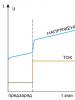
For example, the charge graphs for GP 2700 mAh batteries (age 1.5 years) are shown - Fig. 3, DURACEL 2650mAh (new) - Fig. 4., of unknown origin with the inscription 700 mAh from a radio-controlled car (six months old) - Fig. 5.
Figure 3 shows graphs of battery charge from the camera described at the beginning of the article. As you can see, the batteries were able to deliver only 1210 mAh immediately after charging, the efficiency of the charging process was only about 67%, the batteries had a fairly high internal resistance - 0.52 Ohm (for two batteries connected in series). There was no voltage drop at the end of the fast charge. Since the efficiency of the process was low, the temperature increased quite rapidly throughout the entire time, although the increase in temperature at the end of the charge is still quite obvious.

Rice. 3. GP 2700mAh (age 1.5 years) R in =0.52 Ohm, E charge =1.79A/h, E times =1.21A/h
In Fig. Figure 4 shows charge graphs for DURACEL batteries purchased to replace GP. Here the graphs are like from a textbook - a clear voltage peak with a drop of 5 mV. The temperature practically does not increase during the charging process, and has a very pronounced sharp increase at the end of the charge, with a growth rate of 0.3 ° C/min. The efficiency of the process is about 90%, and the battery resistance is 0.21 Ohm. The camera on one charge of these batteries was able to capture 7GB of photos and videos over two months of intensive use!

Rice. 4 DURACEL 2650mAh (new) R in = 0.21 Ohm, E charge = 2.95 A/h, E times = 2.66 A/h
Well, the last graphs in Fig. 5 shows the charging process of batteries from an unknown Chinese manufacturer. The radio-controlled car, which was equipped with these batteries, practically stopped functioning after six months - the battery charge lasted for 1-2 minutes. As you can see, their actual capacity is only 110mAh, instead of the promised 700mAh. The voltage graph shows that they can hardly be called batteries...

Rice. 5 Unknown 700 mAh (age vn = 0.27 Ohm, E charge = 0.23 A/h, Eraz = 0.11 A/h
The charger requires virtually no adjustment. It may be necessary to adjust the voltage dividers, since a rather large error is possible due to the spread of ratings. To do this, you need to install pre-charged batteries in the charger and turn it on in discharge mode. In this mode, by selecting R6 or R8, calibrate the indicated battery voltage displayed on the HL2 indicator using a reference voltmeter connected directly to the batteries. After this, connect a reference ammeter in series with the batteries, and select R5 or R7 (also in discharge mode) to calibrate the indicated current. The second way is to calibrate with a correction factor inside the program; how and where to change is in the notes of the source.
The firmware of the microcontroller was carried out using a regular LPT programmer consisting of 4 resistors (it can be found on the Internet without much difficulty). Programmed fuses: CKSEL3=CKSEL2=CKSEL1=SUT0=0 – checkboxes. Instead of Atmega 8A, you can use Atmega 8.
When planning the layout of memory elements inside the case, it is necessary to minimize the influence of heating of the batteries from the components of the power supply and board!
When using the charger together with DURACEL batteries, an interesting fact emerged: if the batteries are practically not used for more than a month and a half, their capacity after discharge-charge is only 1700...1800 mAh, however, after one or two discharge-charge cycles, the capacity is restored to 2600 mAh. But nothing helped the old GP and Energizer batteries - over time, their capacity steadily decreased. The conclusion suggests itself - if you don’t use batteries, then do training cycles with them at least once a month.
Hex-codes of the controller firmware, the original project in C (for ), circuit diagram and board layout (), the CHARGER.exe application, its source in Hi-Asm (v.4.03) are attached to the article.
Literature
- Dmitry Mosin. Smart charging of NiMh AA batteries // www.radiokot.ru/circuit/power/charger/10/
- Abramov S.M. Charger for AA batteries //Radioamator. – 2010. - No. 9. – P.36.
- Ridiko L.I. A little about charging NiMH and NiCd batteries // http://caxapa.ru/lib/charge_nimh.pdf
List of radioelements
| Designation | Type | Denomination | Quantity | Note | Shop | My notepad | |
|---|---|---|---|---|---|---|---|
| Picture 1. | |||||||
| DA1 | MK AVR 8-bit | ATmega8 | 1 | To notepad | |||
| DA2 | Linear regulator | LM2940-N | 1 | To notepad | |||
| temperature sensor | DS18B20 | 1 | To notepad | ||||
| VT1, VT4 | MOSFET transistor | IRLL110 | 2 | To notepad | |||
| VT2 | Bipolar transistor | KT814A | 1 | To notepad | |||
| VT3 | Bipolar transistor | KT3107A | 1 | To notepad | |||
| VD1, VD2, VD5, VD6 | Zener diode | 4.5 V | 4 | To notepad | |||
| VD3, VD10 | Schottky diode | 1N5819 | 2 | To notepad | |||
| VD4 | Light-emitting diode | Any red | 1 | To notepad | |||
| VD7-VD9 | Diode | KD522A | 3 | To notepad | |||
| C1, C6 | 1000 µF 16 V | 2 | To notepad | ||||
| C2, C7 | Electrolytic capacitor | 220 µF 25 V | 2 | C7 can be used at 16 V | To notepad | ||
| C3 | Electrolytic capacitor | 100 µF | 1 | To notepad | |||
| C4, C5, C8-C12 | Capacitor | 0.1 µF | 7 | To notepad | |||
| R1, R2, R9, R14, R25, R26 | Resistor | 100 Ohm | 6 | To notepad | |||
| R3, R10, R15 | Resistor | 10 kOhm | 3 | To notepad | |||
| R4 | Resistor | 560 Ohm | 1 | To notepad | |||
| R5, R6 | Resistor | 3 kOhm | 2 | To notepad | |||
| R7, R8 | Resistor | ||||||