Air raid siren diagram. An alarm siren is an effective way to scare off an intruder. What types of sirens are there?
A siren is used for sound notification of any process. As a rule, a siren is heard when an alarming event occurs, but radio amateurs use such sounds in various alarm devices. The tone and frequency of such a sound will force attackers to abandon their bad intentions.
By assembling the siren, we have another goal - to improve skills and experience in the development of electronic devices. Since this siren circuit is quite simple and even a novice radio amateur can do it, we will consider in detail the purpose of all elements of the circuit.

Siren circuit
The siren circuit consists of three, two, a speaker or loudspeaker and a 9 V power source, which can be a crown. The speaker is suitable for a power of up to one watt, with a resistance of 8 ohms.
![]()
How a siren works on two transistors
A latching button or small switch K1 supplies 9 V power to the circuit from the crown. The sound in the BA speaker occurs due to the flow of alternating voltage through its winding, which is generated using a generator built on transistors VT1 and VT2.
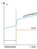
When you press the button K2 without latching, the power source begins to charge the capacitor C1 along the path through the resistor R1. As C1 charges, the potential at the base of VT1 increases and at a certain voltage value the transistor opens, and the sound in the speaker begins to gradually increase. The maximum volume of the siren is achieved when capacitor C1 is fully charged. The rise time of the sound is equal to the charging time of C1, that is, by its capacitance and the resistance of resistor R1.
When button K2 is released, the electrolytic capacitor begins to discharge, and the volume of the siren begins to decrease due to a decrease in the potential at the base of VT1. The discharge time of the capacitor, and accordingly the operating time of the siren, is determined by the capacitance C1, the resistance value of R2 and R3, as well as the resistance of the base-emitter pn junction VT1.
Ceramic capacitor C2 forms positive feedback between the two transistors. By changing the capacitance C2, you can change the tone of the siren on two transistors.

In today's article I want to talk about the air raid siren
The circuit is quite simple and will not be difficult to assemble
I came across a diagram of the Air Raid Siren from the site RadiKot.Ru

The circuit is cool and I decided to assemble it, but as you can see, in order to change the key, you need to press a button. I thought about how this could be automated, I thought about it and came up with it. Remember, I wrote about , and that’s what will work in this scheme. This is what I got now

Minimum details, maximum effect:
R1 = 68k
R2 = 51k
R3 = 22k
R4.5 = 10k
VT1= KT315
VT2= P217
VT3,4= S9014
The speaker used was 5 W 16 Ohm from a disassembled TV
I was pleased with the result, but the neighbors screamed for a long time afterwards. It's good that they don't know who did it. Good luck with the build
Related Posts
I took the 3GDSH-1 speakers out of the TVs so that they wouldn’t lie idle and decided to make speakers, but since I have an external amplifier with a subwoofer, that means I’ll be assembling satellites.
Hello everyone, dear radio amateurs and audiophiles! Today I will tell you how to modify the high-frequency speaker 3GD-31 (-1300) also known as 5GDV-1. They were used in such acoustic systems as 10MAS-1 and 1M, 15MAS, 25AS-109…….
Hello dear readers. Yes, it’s been a while since I wrote a blog post, but with all responsibility I want to say that now I will try to keep up and will write reviews and articles…….
Hello dear visitor. I know why you are reading this article. Yes, yes I know. No what are you? I'm not a telepath, I just know why you ended up on this page. Surely......
And again, my friend Vyacheslav (SAXON_1996) wants to share his work on speakers. Word to Vyacheslav I somehow got one 10MAC speaker with a filter and a high-frequency speaker. I haven’t…… for a long time.
To sound children's toys, motorcycles and battery-powered cars, I suggest you make a simple circuit of a sound device that simulates the signal of a “Police siren”. The circuit is simple, contains a small number of parts and does not require configuration. It is not difficult to assemble; you can order stitched microcontrollers using the link at the end of the article.
The siren device is assembled on a programmable microcontroller PIC16F628.
The firmware has two different sirens and a “Quack”.
Schematic diagram of a siren with a power amplifier

Siren circuit board with PA

How to use a siren?
When you press the “Quack” button, a one-time imitation of the “Police Quack” is activated. When you press the “Start” button, “Siren No. 1” turns on, when you press it again, “Siren No. 2” turns on. There is also an effect that simulates the end of the sound of the first siren; to turn on this effect, click the “End” button. To stop playing a sound effect, press the Stop button. This circuit is easy to assemble and does not require configuration.
“UM” – Power amplifier, circuit above. This circuit is assembled on a printed circuit board; there is also a simple stabilizer on the printed circuit board to power the microcontroller.
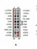
The buttons for this device were taken from the panel of an old car radio, but simple tact buttons can also be used.
You will also need a PIC programmer. There are many different programmer schemes on the Internet.
A USB or COM port is usually used for data transfer.
You can buy a ready-made programmer that you need inexpensively in China.
Modification: “Quack with flashing light”
If you wish, you can also add an LED flasher on the PIC12F675 to the “quack” circuit!

Photo of the assembled board with a flasher


Video of a siren and flasher working
If you want to assemble the proposed siren with a flasher, you can purchase a kit for its assembly with stitched microcircuits at the link: vsmaster.ru

Sergey V. Kamyshin. (For all questions: [email protected])
P O P U L A R N O E:
Schemes of simple sound moisture alarms on the NE555 timer
This device can be used to detect moisture, for example in the soil or alert about wet diapers of a baby, etc.
The sound generator is triggered when water hits the sensor or high humidity appears.
Electrical connection diagram of the harnesses of the LADA GRANTA VAZ-2190 car
If you have a schematic diagram of the car VAZ-2190 (GRANT) and a multimeter or voltmeter (up to 15V), or even (
A simple two-tone siren circuit.
This two-tone siren circuit is simple, easily repeatable, and can be used to provide sound signals from any car security system. It is implemented using elements of domestic production and does not contain any deficiencies. The schematic diagram of the device is shown in the figure below:

The circuit is built on one logical chip K561LA7. The third and fourth elements form a symmetrical multivibrator, from the output of which the signal through the amplifier stage on transistor VT1 is supplied to the high-frequency head. The head can be used with a resistance of 2...8 Ohms. The frequency of the generated signal depends on the ratings of C4, R3 and C3, R4, and it is desirable that the rating of R3 be equal to the rating of R4. With the ratings of these elements indicated in the diagram, the generation frequency will be approximately 900 Hz.
A multivibrator is also assembled on the first two elements of the microcircuit, its frequency is 2 Hz. Thus, if there is a logical one at its output (pin 4 of the microcircuit), the second multivibrator will produce a signal with a frequency of 900 Hz. With a logical zero on the 4th leg of the microcircuit, the generation frequency will increase to approximately 1100...1200 Hz. As a last resort, if you don’t like the tone of the siren’s sound, play with the values of the above elements of the second multivibrator (which is at 900 Hz). The frequency of the first multivibrator depends on the ratings of C1 and R1.
The supply voltage of this circuit is limited by the maximum permissible parameters of the microcircuit, and, according to the technical specifications for K561LA7, can be in the range from 5 to 15 Volts, but keep in mind that as the supply voltage decreases, the volume of the siren will also decrease. When the supply voltage of the circuit is 12 Volts, the volume should be no less than that of a standard, for example, Zhigulevsky, car signal. The current consumption of the device when turned on is about 0.5 Ampere.
Just in case, we present the location of the pins of the K561LA7 microcircuit. Picture below:

Setting up the “Two-tone siren” circuit.
As we wrote above, the frequency of the main multivibrator is set by resistors R3 and R4, and if you practice with their values, remove one leg of the diode VD1 and make a selection. Then connect resistor R2 in parallel with R3, with the value of which select the desired frequency of the high-pitched sound of the siren. Solder the VD1 diode leg into place. By changing the value of resistor R1, you can select the desired frequency of changing the high and low tones of the siren. That's basically the whole setup. Otherwise, you don’t need to configure anything else, and if you didn’t mess anything up during assembly, it will work right away. We wish you success in repeating.
A siren is used to produce a powerful and strong sound signal to attract people's attention and is used in fire alarm and automation systems, as well as in combination with alarm devices at various protected sites.

Generators in the diagram are marked with a yellow frame. The first G1 sets the frequency of tone changes, and the second G2 actually sets the tone itself, which smoothly changes on the transistor VT1 connected in series with resistance R2. To select the desired sound, instead of resistances R1, R2, you can use trimming resistors of the same values.

When the power supply is turned on, the sound emitter begins to generate a tonal acoustic signal, the pitch changes from high to low and back. The signal sounds continuously, only the tone of the sound changes, which switches at a frequency of 3-4 Hz.

The siren circuit uses two multivibrators on elements D1.1 and D1.2 of the K561LN2 microcircuit, which controls the tone, and a multivibrator on elements D1.3 and D1.4 of the same microcircuit, generating tonal signals. The pulse frequency generated by the first multivibrator on elements D1.3 and D1.4 depends on elements C2, R2 and C3, R4. You can change the pulse repetition rate, and therefore the tone of the audio signal, using both resistances and capacitors.
Suppose that at the initial moment at the output of the multivibrator there is a logical one level at elements D1.1 and D1.2. Since positive is supplied to the cathodes of diodes VD1 and VD2, the diodes will be locked. Resistors R4 and R5 do not participate in the operation of the circuit and the frequency at the multivibrator output is minimal, a low-tone signal sounds.
As soon as the output of these elements is set to logical zero, the diodes VD1 and VD2 open and connect resistances R4 and R5. As a result, the frequency at the multivibrator output will increase.
The KT815 transistors used in the circuit can be replaced with KT817, and KT814 with KT816. Diodes - KD521, KD522, KD503, KD102.
The following device can be used as a hazard warning light or horn for a mountain bike. It is a two-tone siren and consists of a clock generator on elements DD1.1-DD1.3, two tone generators (the first on elements DD2.1, DD2.2 and the second on elements DD2.3, DD2.4), a matching stage with power amplifier based on element DD1.4 and transistor VT1.

The circuit consists of two generators. The first is used for tone generation, the second for modification and modulation.
For the maximum volume level, it is necessary that the piezoelement receive a frequency equivalent to its resonant frequency via a bridge circuit.
The basis of the design is a powerful multivibrator 4047, operating in an astable mode. All this is controlled by a powerful MOSFET transistor VT1, which is controlled by the NE555 timer, by generating corresponding low frequency rectangular pulses, resulting in a fire siren. Switching operating modes continuously or intermittently is set using a toggle switch.

Pins 10 and 11 of the 4047 microassembly produce antiphase signals from which they control a bridge on four MOSFETs. To obtain maximum volume, that is, set the resonant frequency of the piezoelectric element, a tuning resistance R6 was added to the design.
This circuit is made up of a combination of a musical synthesizer on a UMS-8-08 microcircuit with a powerful output stage of an electronic siren. To start the circuit, a relay is used, the winding of which is galvanically isolated from the rest of the circuit.

The UMS chip has a standard connection diagram. Three push-button switches S1-S3 make it possible to configure the microcircuit to play one of the melodies. When you click on the first button, the melody starts playing, and by clicking on the third you can sort through the melodies and select the one you need.

A selection of several siren circuits on PIC microcontrollers
This circuit is a simple multi-tone siren based on the UM3561 microassembly

The circuit uses an 8 Ohm speaker with a power of 0.5 W. Using two switches, you can select and play different alarm tones. Each position generates its own sound effect.