Electric motor speed controller: principle of operation. Power tool motor speed controller - diagram and principle of operation How to make an electric motor rotate
On simple mechanisms it is convenient to install analog current regulators. For example, they can change the speed of rotation of the motor shaft. From the technical side, implementing such a regulator is simple (you will need to install one transistor). Suitable for adjusting independent speed of motors in robotics and power supplies. The most common types of regulators are single-channel and two-channel.
Video No. 1. Single-channel regulator in operation. Changes the rotation speed of the motor shaft by rotating the variable resistor knob.
Video No. 2.
Increasing the rotation speed of the motor shaft when operating a single-channel regulator. An increase in the number of revolutions from the minimum to the maximum value when rotating the variable resistor knob. Video No. 3.
Two-channel regulator in operation. Independent setting of the torsion speed of motor shafts based on trimming resistors.
Video No. 4.
The voltage at the regulator output was measured with a digital multimeter. The resulting value is equal to the battery voltage, from which 0.6 volts have been subtracted (the difference arises due to the voltage drop across the transistor junction). When using a 9.55 volt battery, a change from 0 to 8.9 volts is recorded.
Functions and main characteristics
The load current of single-channel (photo 1) and two-channel (photo 2) regulators does not exceed 1.5 A. Therefore, to increase the load capacity, the KT815A transistor is replaced with KT972A. The pin numbering for these transistors is the same (e-k-b). But the KT972A model is operational with currents up to 4A.
Single channel motor controller
The device controls one motor, powered by voltage in the range from 2 to 12 volts.
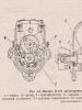
Device design The main design elements of the regulator are shown in the photo. 3. The device consists of five components: two variable resistance resistors with a resistance of 10 kOhm (No. 1) and 1 kOhm (No. 2), a transistor model KT815A (No. 3), a pair of two-section screw terminal blocks for the output for connecting a motor (No. 4) and input for connecting a battery (No. 5).
Note 1.
The operating procedure of the motor controller is described in the electrical diagram (Fig. 1). Taking into account the polarity, a constant voltage is supplied to the XT1 connector. The light bulb or motor is connected to the XT2 connector. A variable resistor R1 is turned on at the input; rotating its knob changes the potential at the middle output as opposed to the minus of the battery. Through current limiter R2, the middle output is connected to the base terminal of transistor VT1. In this case, the transistor is switched on according to a regular current circuit. The positive potential at the base output increases as the middle output moves upward from the smooth rotation of the variable resistor knob. There is an increase in current, which is due to a decrease in the resistance of the collector-emitter junction in transistor VT1. The potential will decrease if the situation is reversed.
 Electrical circuit diagram
 Materials and details
A printed circuit board measuring 20x30 mm is required, made of a fiberglass sheet foiled on one side (permissible thickness 1-1.5 mm). Table 1 provides a list of radio components.
Note 2. The variable resistor required for the device can be of any manufacture; it is important to observe the current resistance values for it indicated in Table 1.
Note 3. To regulate currents above 1.5A, the KT815G transistor is replaced with a more powerful KT972A (with a maximum current of 4A). In this case, the printed circuit board design does not need to be changed, since the distribution of pins for both transistors is identical.
Build process
For further work, you need to download the archive file located at the end of the article, unzip it and print it. The regulator drawing (file) is printed on glossy paper, and the installation drawing (file) is printed on a white office sheet (A4 format).
Next, the drawing of the circuit board (No. 1 in photo. 4) is glued to the current-carrying tracks on the opposite side of the printed circuit board (No. 2 in photo. 4). It is necessary to make holes (No. 3 in photo. 14) on the installation drawing in the mounting locations. The installation drawing is attached to the printed circuit board with dry glue, and the holes must match. Photo 5 shows the pinout of the KT815 transistor. 
The input and output of terminal blocks-connectors are marked in white. A voltage source is connected to the terminal block via a clip. A fully assembled single-channel regulator is shown in the photo. The power source (9 volt battery) is connected at the final stage of assembly. Now you can adjust the shaft rotation speed using the motor; to do this, you need to smoothly rotate the variable resistor adjustment knob.
To test the device, you need to print a disk drawing from the archive. Next, you need to paste this drawing (No. 1) onto thick and thin cardboard paper (No. 2). Then, using scissors, a disc is cut out (No. 3).
The resulting workpiece is turned over (No. 1) and a square of black electrical tape (No. 2) is attached to the center for better adhesion of the surface of the motor shaft to the disk. You need to make a hole (No. 3) as shown in the image. Then the disk is installed on the motor shaft and testing can begin. The single-channel motor controller is ready!
Two-channel motor controller
Used to independently control a pair of motors simultaneously. Power is supplied from a voltage ranging from 2 to 12 volts. The load current is rated up to 1.5A per channel.
Single channel motor controller
The main components of the design are shown in photo.10 and include: two trimming resistors for adjusting the 2nd channel (No. 1) and the 1st channel (No. 2), three two-section screw terminal blocks for output to the 2nd motor (No. 3), for output to the 1st motor (No. 4) and for input (No. 5).
Note:1 Installation of screw terminal blocks is optional. Using a thin stranded mounting wire, you can connect the motor and power source directly.
Note 1.
The circuit of a two-channel regulator is identical to the electrical circuit of a single-channel regulator. Consists of two parts (Fig. 2). The main difference: the variable resistance resistor is replaced with a trimming resistor. The rotation speed of the shafts is set in advance. 
Note.2.
Materials and details
To quickly adjust the rotation speed of the motors, the trimming resistors are replaced using a mounting wire with variable resistance resistors with the resistance values indicated in the diagram.
Build process
You will need a printed circuit board measuring 30x30 mm, made of a fiberglass sheet foiled on one side with a thickness of 1-1.5 mm. Table 2 provides a list of radio components.
After downloading the archive file located at the end of the article, you need to unzip it and print it. The regulator drawing for thermal transfer (termo2 file) is printed on glossy paper, and the installation drawing (montag2 file) is printed on a white office sheet (A4 format).
Any of the inputs is connected to the pole of the power source (a 9-volt battery is shown in the example). The negative of the power supply is attached to the center of the terminal block. It is important to remember: the black wire is “-” and the red wire is “+”.
The motors must be connected to two terminal blocks, and the desired speed must also be set. After successful testing, you need to remove the temporary connection of the inputs and install the device on the robot model. The two-channel motor controller is ready!
The necessary diagrams and drawings for the work are presented. The emitters of the transistors are marked with red arrows.
When starting the electric motor, the current consumption exceeds 7 times, which contributes to premature failure of the electrical and mechanical parts of the motor. To prevent this, you should use an electric motor speed controller. There are many factory-made models, but in order to make such a device yourself, you need to know the principle of operation of the electric motor and how to regulate rotor speed.
General information
AC electric motors have become widespread in many areas of human activity, namely asynchronous models. The main purpose of the engine as an electric machine is transformation of electrical energy into mechanical energy. Asynchronous in translation means non-simultaneous, since the rotor speed differs from the frequency of the alternating voltage (U) in the stator. There are two types of asynchronous motors based on the type of power supply:
- Single-phase.
- Three-phase.
Single-phase ones are used for household needs, and three-phase ones are used in production. Three-phase asynchronous motors (hereinafter referred to as TAM) use two types of rotors:
- closed;
- phase
Closed motors make up about 95% of all motors used and have significant power (from 250 W and above). The phase type is structurally different from the IM, but is used quite rarely compared to the first. The rotor is a cylindrical steel figure that is placed inside the stator, with a core pressed onto its surface.
Squirrel cage and wound rotors
Highly conductive copper (for high-power machines) or aluminum rods (for lower-power machines) soldered or poured into the surface of the core and short-circuited at the ends with two rings play the role of electromagnets with poles facing the stator. The winding rods do not have any insulation, since the voltage in such a winding is zero.
More commonly used for mid-power motor cores, aluminum has low density and high electrical conductivity.
To reduce higher harmonics of electromotive force (EMF) and eliminate magnetic field pulsation the rotor rods have a certain calculated angle of inclination relative to the axis of rotation. If a low-power electric motor is used, the grooves are closed structures that separate the rotor from the gap in order to increase the inductive component of the resistance.
The rotor in the form of a phase design or type is characterized by a winding, its ends are connected in a star type and attached to slip rings (on the shaft), along which graphite brushes slide. To eliminate eddy currents, the surface of the windings is covered with an oxide film. In addition, a resistor is added to the rotor winding circuit, which allows you to change the active resistance (R) of the rotor circuit to reduce the values of inrush currents (Ip). Starting currents negatively affect the electrical and mechanical parts of the electric motor. Variable resistors used to regulate Ip:
- Metal or stepped with manual switching.
- Liquid (due to immersion to the depth of the electrodes).
Graphite brushes are subject to wear, and some models are equipped with a squirrel-cage design that lifts the brushes and closes the rings after the motor starts. IMs with a wound rotor are more flexible in terms of regulation of Ip.
Design features
An asynchronous motor does not have pronounced poles, unlike a DC electric motor. Number of poles determined by the number of coils in the windings fixed part (stator) and connection method. In an asynchronous machine with 4 coils, a magnetic flux passes through. The stator is made of special steel sheets (electrical steel), which reduce eddy currents to zero, at which significant heating of the windings occurs. It leads to a massive interturn short circuit.
The iron ore or rotor core is pressed directly onto the shaft. There is a minimum air gap between the rotor and stator. The rotor winding is made in the form of a “squirrel cage” and is made of copper or aluminum rods.
In electric motors with a power of up to 100 kW, aluminum, which has low density, is used to fill the grooves of the rotor core. But despite this device, engines of this type get hot. To solve this problem fans are used for forced cooling, which are mounted on the shaft. These engines are simple and reliable. However, motors consume a large current when starting, 7 times the rated current. Because of this, they have a low starting torque, since most of the electrical energy goes to heating the windings.
Electric motors, which have an increased starting torque, differ from ordinary asynchronous ones in the design of the rotor. The rotor is made in the form of a double “squirrel cage”. These models are similar to the phase types of rotor manufacturing. It consists of an inner and outer “squirrel cage”, and the outer one is the starting one and has a large active and small reactive R. The outer one has a slight active and high reactive R. As the rotation speed increases, I switches to the inner cage and operates in the form of a squirrel-cage rotor.
Principle of operation
When I flows through the stator winding, a magnetic flux (F) is created in each of them. These F are shifted by 120 degrees relative to each other. The resulting F is rotating, creating electromotive force (EMF) in aluminum or copper conductors. As a result of this, a starting magnetic moment of the electric motor is created, and the rotor begins to rotate. This process is also called slip (S) in some sources, showing the frequency difference n1 of the electromagnetic field of the starter, which becomes greater than the frequency obtained when rotor n2 rotates. It is calculated as a percentage and has the form: S = ((n1-n2)/n1) * 100%.
Scheme 1 - Thyristor speed control of a commutator motor without loss of power.
This circuit performs regulation by opening or closing thyristors (triacs) during a phase transition through the neutral. To correctly control a commutator motor, the following methods of modifying circuit 1 are used:
- Installation of LRC protective circuits consisting of capacitors, resistors and chokes.
- Adding capacitance at the input.
- The use of thyristors or triacs, the current of which exceeds the rated value of the motor current in the range of 3..8 times.
This type of regulator has advantages and disadvantages. The first include low cost, low weight and dimensions. The second ones include the following:
- application for low power motors;
- there is noise and jerking of the motor;
- when using a circuit based on triacs, a constant U occurs on the motor.
This type of regulator is installed in fans, air conditioners, washing machines and electric drills. Performs its functions perfectly, despite its shortcomings.
Transistor type
Another name for a transistor-type regulator is an autotransformer or PWM regulator (scheme 2). It changes the value of U according to the principle of pulse width modulation (PWM) using an output stage that uses IGBT transistors.
Scheme 2 - Transistor PWM speed controller.
Switching of transistors occurs at a high frequency and thanks to this it is possible to change the width of the pulses. Consequently, the value of U will also change. The longer the pulse and the shorter the pause, the higher the value of U and vice versa. The positive aspects of using this variety are as follows:
- Low weight of the device with small dimensions.
- Quite low cost.
- At low speeds there is no noise.
- Control via low U values (0..12 V).
The main disadvantage of the application is that the distance to the electric motor should be no more than 4 meters.
Frequency regulation
Scheme 3 - Frequency speed controller.
A specialized inverter has its advantages and disadvantages. The advantages are the following:
- Blood pressure control without human intervention.
- Stability.
- Additional features.
It is possible to control the operation of the electric motor under certain conditions, as well as protection against overloads and short-circuit currents. In addition, it is possible to expand the functionality by connecting digital sensors, monitoring operating parameters and using a PID controller. The disadvantages include limitations in frequency control and a fairly high cost.
For three-phase IM, frequency control devices are also used (Scheme 4). The regulator has three phases at the output for connecting an electric motor.
Scheme 4 - Inverter for a three-phase motor.
This option also has its strengths and weaknesses. The first include the following: low cost, choice of power, wide range of frequency regulation, as well as all the advantages of single-phase frequency converters. Among all the negative aspects, the main ones can be identified: preliminary selection and heating during startup.
DIY making
If there is no opportunity or desire to purchase a factory-type regulator, then you can assemble it yourself. Although regulators of the “tda1085” type have proven themselves very well. To do this, you need to familiarize yourself with the theory in detail and start practicing. Triac circuits are very popular, in particular the speed controller of a 220V asynchronous motor (diagram 5). It's not difficult to make. It is assembled on a VT138 triac, which is well suited for these purposes.
Scheme 5 - A simple speed controller on a triac.
This regulator can also be used to adjust the speed of a 12-volt DC motor, as it is quite simple and universal. The speed is regulated by changing the parameters P1, which determines the phase of the incoming signal, which opens the transition of the triac.
The operating principle is simple. When the engine starts, it slows down, the inductance changes downward and contributes to an increase in U in the “R2->P1->C2” circuit. When C2 is discharged, the triac opens for some time.
There is another scheme. It works a little differently: by providing a reverse type of energy flow, which is optimally beneficial. The circuit includes a fairly powerful thyristor.
Scheme 6 - Design of a thyristor regulator.
The circuit consists of a control signal generator, an amplifier, a thyristor and a circuit section that functions as a rotor rotation stabilizer.
The most universal circuit is a regulator based on a triac and dinistor (scheme 7). It is able to smoothly reduce the shaft rotation speed, reverse the motor (change the direction of rotation) and reduce the starting current.
The principle of operation of the circuit:
- C1 is charged until U breakdown of dinistor D1 through R2.
- When D1 breaks, it opens the junction of triac D2, which is responsible for controlling the load.
The load voltage is directly proportional to the frequency component when D2 opens, which depends on R2. The circuit is used in vacuum cleaners. It contains universal electronic control, as well as the ability to easily connect 380 V power. All parts should be placed on a printed circuit board made using laser-iron technology (LUT). You can find out more about this board manufacturing technology on the Internet.
Thus, when choosing an electric motor speed controller, you can buy a factory one or make it yourself. Making a homemade regulator is quite simple, since if you understand the principle of operation of the device, you can easily assemble it. In addition, you should follow safety rules when installing parts and when working with electricity.
Any modern power tool or household appliance uses a commutator motor. This is due to their versatility, i.e. the ability to work from both alternating and direct voltage. Another advantage is the efficient starting torque.
However, the high speed of the commutator motor does not suit all users. For a smooth start and the ability to change the speed of rotation, a regulator was invented, which is quite possible to make with your own hands.
Operating principle and types of commutator motors
Each electric motor consists of a commutator, stator, rotor and brushes. The principle of its operation is quite simple:
In addition to the standard device, there are also:

Regulator device
There are many schemes of such devices in the world. Nevertheless, they can all be divided into 2 groups: standard and modified products.
Standard device
Typical products are distinguished by the ease of manufacture of the idynistor and good reliability when changing engine speed. As a rule, such models are based on thyristor regulators. The operating principle of such schemes is quite simple:

Thus, the speed of the commutator motor is adjusted. In most cases, a similar scheme is used in foreign household vacuum cleaners. However, you should know that such a speed controller does not have feedback. Therefore, when the load changes, you will have to adjust the speed of the electric motor.
Changed schemes
 Of course, the standard device suits many fans of speed controllers to “dig” into the electronics. However, without progress and improvement of products, we would still be living in the Stone Age. Therefore, more interesting schemes are constantly being invented, which many manufacturers are happy to use.
The most commonly used are rheostat and integral regulators. As the name implies, the first option is based on a rheostat circuit. In the second case, an integral timer is used.
Rheostatic ones are effective in changing the number of revolutions of the commutator motor. High efficiency is due to power transistors, which take part of the voltage. Thus, the current flow is reduced and the motor works with less effort.
Video: speed control device with power maintenance
The main disadvantage of this scheme is the large amount of heat generated. Therefore, for smooth operation, the regulator must be constantly cooled. Moreover, the cooling of the device must be intensive.
 A different approach is implemented in an integral regulator, where an integral timer is responsible for the load. As a rule, transistors of almost any type are used in such circuits. This is due to the fact that it contains a microcircuit with large output current values.
If the load is less than 0.1 ampere, then all the voltage goes directly to the microcircuit, bypassing the transistors. However, for the regulator to operate effectively, it is necessary that there be a voltage of 12V at the gate. Therefore, the electrical circuit and the supply voltage itself must correspond to this range.
Overview of typical circuits
 You can regulate the rotation of the shaft of a low-power electric motor by connecting a power resistor in series with no. However, this option has very low efficiency and the inability to smoothly change speed. To avoid such a nuisance, you should consider several regulator circuits that are used most often.
As you know, PWM has a constant pulse amplitude. In addition, the amplitude is identical to the supply voltage. Consequently, the electric motor will not stop even when running at low speeds.
The second option is similar to the first. The only difference is that an operational amplifier is used as the master oscillator. This component has a frequency of 500 Hz and produces triangular-shaped pulses. Adjustment is also carried out using a variable resistor.
How to make it yourself
 If you don’t want to spend money on purchasing a ready-made device, you can make it yourself. This way, you can not only save money, but also gain useful experience. So, to make a thyristor regulator you will need:
- soldering iron (to check functionality);
- wires;
- thyristor, capacitors and resistors;
- scheme.
As can be seen from the diagram, the regulator controls only 1 half-cycle. However, for testing performance on a regular soldering iron, this will be quite enough.
If you don’t have enough knowledge to decipher the diagram, you can familiarize yourself with the text version:

The use of regulators allows for more economical use of electric motors. In certain situations, such a device can be made independently. However, for more serious purposes (for example, monitoring heating equipment), it is better to purchase a ready-made model. Fortunately, there is a wide selection of such products on the market, and the price is quite affordable.
Do you have an angle grinder, but no speed controller? You can make it yourself.
Speed controller and soft start for grinder
Both are necessary for reliable and convenient operation of the power tool.
What is a speed controller and what is it for?
This device is designed to control the power of an electric motor. With its help you can regulate the speed of rotation of the shaft. The numbers on the adjustment wheel indicate a change in the rotation speed of the disk.
The regulator is not installed on all angle grinders.
Grinders with speed controller: examples in the photo


The lack of a regulator greatly limits the use of the grinder. The rotation speed of the disk affects the quality of the grinder and depends on the thickness and hardness of the material being processed.
If the speed is not regulated, then the speed is constantly kept at maximum. This mode is only suitable for hard and thick materials, such as corners, pipes or profiles. Reasons why a regulator is necessary:
- Thin metal or soft wood requires a lower rotation speed. Otherwise, the edge of the metal will melt, the working surface of the disk will become washed out, and the wood will turn black from the high temperature.
- To cut minerals, it is necessary to regulate the speed. Most of them break off small pieces at high speed and the cutting area becomes uneven.
- To polish cars, you do not need the highest speed, otherwise the paintwork will deteriorate.
- To change a disk from a smaller diameter to a larger one, you need to reduce the speed. It is almost impossible to hold a grinder with your hands with a large disk rotating at high speed.
- Diamond blades should not be overheated to avoid damaging the surface. To do this, the speed is reduced.
Why do you need a soft start?
The presence of such a launch is a very important point. When starting a powerful power tool connected to the network, a surge of inrush current occurs, which is many times higher than the rated current of the motor, and the voltage in the network sags. Although this surge is short-lived, it causes increased wear on the brushes, motor commutator and all tool elements through which it flows. This can cause failure of the tool itself, especially Chinese ones, with unreliable windings that can burn out during switching on at the most inopportune moment. There is also a large mechanical jerk during startup, which leads to rapid wear of the gearbox. Such a start extends the life of the power tool and increases the level of comfort during operation.
Electronic unit in an angle grinder
The electronic unit allows you to combine the speed controller and soft start into one. The electronic circuit is implemented on the principle of pulse-phase control with a gradual increase in the opening phase of the triac. Grinders of different power and price categories can be equipped with such a block.
Types of devices with an electronic unit: examples in the table
Angle grinders with an electronic unit: popular in the photo


DIY speed controller
The speed controller is not installed in all models of angle grinders. You can make a block for regulating the speed with your own hands or purchase a ready-made one.
Factory speed controllers for angle grinders: photo examples

 Bosh angle grinder speed controller
  Speed controller for angle grinders Sturm
 Speed controller for angle grinders DWT
Such regulators have a simple electronic circuit. Therefore, creating an analogue with your own hands will not be difficult. Let's look at what the speed controller for grinders up to 3 kW is assembled from.
PCB manufacturing
The simplest diagram is presented below.
Since the circuit is very simple, there is no point in installing a computer program for processing electrical circuits just because of it. Moreover, special paper is needed for printing. And not everyone has a laser printer. Therefore, we will take the simplest route of manufacturing a printed circuit board.
Take a piece of PCB. Cut to the size required for the chip. Sand the surface and degrease. Take a laser disc marker and draw a diagram on the PCB. To avoid mistakes, draw with a pencil first. Next, we start etching. You can buy ferric chloride, but the sink is difficult to clean after it. If you accidentally drop it on your clothes, it will leave stains that cannot be completely removed. Therefore, we will use a safe and cheap method. Prepare a plastic container for the solution. Pour in 100 ml hydrogen peroxide. Add half a tablespoon of salt and a packet of citric acid up to 50 g. The solution is made without water. You can experiment with proportions. And always make a fresh solution. All copper should be removed. This takes about an hour. Rinse the board under running water. Drill the holes.
It can be made even simpler. Draw a diagram on paper. Glue it with tape to the cut out PCB and drill holes. And only after that draw the circuit with a marker on the board and etch it.
Wipe the board with alcohol-rosin flux or a regular solution of rosin in isopropyl alcohol. Take some solder and tin the tracks.
Installation of electronic components (with photo)
Prepare everything you need to mount the board:
- Solder spool.
- Pins to the board.
- Triac bta16.
- 100 nF capacitor.
- Fixed resistor 2 kOhm.
- Dinistor db3.
- Variable resistor with linear dependence at 500 kOhm.
Cut off four pins and solder them onto the board. Then install the dinistor and all other parts except the variable resistor. Solder the triac last. Take a needle and brush. Clean the gaps between the tracks to remove any possible shorts. The triac with its free end with a hole is attached to an aluminum radiator for cooling. Use fine sandpaper to clean the area where the element is attached. Take KPT-8 brand heat-conducting paste and apply a small amount of paste to the radiator. Secure the triac with a screw and nut. Since all the parts of our design are under mains voltage, we will use a handle made of insulating material for adjustment. Put it on a variable resistor. Use a piece of wire to connect the outer and middle terminals of the resistor. Now solder two wires to the outer terminals. Solder the opposite ends of the wires to the corresponding pins on the board.
You can make the entire installation hinged. To do this, we solder the parts of the microcircuit to each other directly using the legs of the elements themselves and the wires. Here you also need a radiator for the triac. It can be made from a small piece of aluminum. Such a regulator will take up very little space and can be placed in the body of the angle grinder.
If you want to install an LED indicator in the speed controller, then use a different circuit.
Regulator circuit with LED indicator.
Diodes added here:
- VD 1 - diode 1N4148;
- VD 2 - LED (operation indication).
Assembled regulator with LED.
This unit is designed for low-power angle grinders, so the triac is not installed on the radiator. But if you use it in a powerful tool, then do not forget about the aluminum board for heat transfer and the bta16 triac.
Making a power regulator: video
Electronic unit testing
Before connecting the unit to the instrument, let's test it. Take the overhead socket. Install two wires into it. Connect one of them to the board, and the second to the network cable. The cable has one more wire left. Connect it to the network card. It turns out that the regulator is connected in series to the load power circuit. Connect a lamp to the circuit and check the operation of the device.
Testing the power regulator with a tester and a lamp (video)
Connecting the regulator to the grinder
The speed controller is connected to the tool in series.
The connection diagram is shown below.
If there is free space in the handle of the grinder, then our block can be placed there. The surface-mounted circuit is glued with epoxy resin, which serves as an insulator and protection against shaking. Bring the variable resistor with a plastic handle out to regulate the speed.
Installing the regulator inside the angle grinder body: video
The electronic unit, assembled separately from the angle grinder, is housed in a housing made of insulating material, since all elements are under mains voltage. A portable socket with a network cable is screwed to the case. The handle of the variable resistor is displayed outside.
The regulator is plugged into the network, and the instrument is plugged into a portable socket.
Speed regulator for an angle grinder in a separate case: video
Usage
There are a number of recommendations for the correct use of an angle grinder with an electronic unit. When starting the tool, let it accelerate to the set speed, do not rush to cut anything. After turning off, restart it after a few seconds so that the capacitors in the circuit have time to discharge, then the restart will be smooth. You can adjust the speed while the grinder is operating by slowly turning the variable resistor knob.
The good thing about a grinder without a speed controller is that without serious expenses you can make a universal speed controller for any power tool yourself. The electronic unit, mounted in a separate box, and not in the body of the grinding machine, can be used for a drill, drill, or circular saw. For any tool with a commutator motor. Of course, it’s more convenient when the control knob is on the instrument, and you don’t have to go anywhere or bend over to turn it. But here it’s up to you to decide. It's a matter of taste.
The engine speed controller is needed to perform smooth acceleration and braking. Such devices have become widespread in modern industry. Thanks to them, the speed of movement in the conveyor, on various devices, as well as when the fan rotates, is measured. Motors with 12 Volt performance are used in entire control systems and in cars.
System design
Commutator motor type consists mainly of a rotor, a stator, as well as brushes and a tachogenerator.
- The rotor is part of the rotation, the stator is an external type of magnet.
- Brushes, which are made of graphite, are the main part of the sliding contact, through which voltage is applied to the rotating armature.
- A tachogenerator is a device that monitors the rotation characteristics of the device. If there is a violation in the regularity of the rotation process, then it adjusts the voltage level entering the engine, thereby making it smoother and slower.
- Stator. Such a part may include not one magnet, but, for example, two pairs of poles. At the same time, instead of static magnets, there will be coils of electromagnets. Such a device is capable of performing work both from direct current and alternating current.
Scheme of the speed controller of the commutator motor
 Special frequency converters are used in the form of speed controllers for 220 V and 380 V electric motors . Such devices are classified as high-tech, they help to make a fundamental transformation of the current characteristics (signal shape, as well as frequency). They are equipped with powerful semiconductor transistors, as well as a pulse-width modulator. The entire process of operating the device occurs through the control of a special unit on a microcontroller. The change in speed in the rotation of the motor rotor occurs quite slowly.
It is for this reason that frequency converters are used in loaded devices. The slower the acceleration process occurs, the less load will be placed on the gearbox, as well as the conveyor. In all frequency generators you can find several degrees of protection: by load, current, voltage and other indicators.
Some models of frequency converters supply power from a single-phase voltage (it will reach 220 Volts) and create a three-phase voltage from it. This helps to connect an asynchronous motor at home without the use of particularly complex circuits and designs. In this case, the consumer will not lose power while working with such a device.
Why use such a device-regulator?
If we talk about regulator motors, then the revolutions needed are:

The circuits used to create frequency converters in an electric motor are widely used in most household devices. Such a system can be found in wireless power supplies, welding machines, phone chargers, power supplies for personal computers and laptops, voltage stabilizers, lamp ignition units for backlighting modern monitors, as well as LCD TVs.
220V electric motor speed controller
You can make it completely yourself, but for this you will need to study all possible technical features of the device. By design, several types of main parts can be distinguished. Namely:
- The electric motor itself.
- Microcontroller control system for the conversion unit.
- Drive and mechanical parts that are associated with the operation of the system.
 Just before starting the device, after applying a certain voltage to the windings, the process of rotating the engine begins with maximum power. It is this feature that will distinguish asynchronous devices from other types. On top of everything else, the load from the mechanisms that set the device in motion is added. Ultimately, at the initial stage of operation of the device, the power, as well as the current consumption, only increases to the maximum level.
At this time, the process of releasing the greatest amount of heat occurs. Overheating occurs in the windings, as well as in the wires. Using Partial Transformation will help prevent this from happening. If you install a soft start, then to the maximum speed mark (which can also be adjusted by equipment and may not be 1500 rpm, but only 1000), the engine will begin to accelerate not at the first moment of operation, but over the next 10 seconds (at the same time, every second the device will add 100-150 revolutions). At this time, the load on all mechanisms and wires begins to decrease several times.
How to make a regulator with your own hands
You can completely independently create an electric motor speed controller of about 12 V. For this you should use switch of several positions at once, as well as a special wirewound resistor. With the help of the latter, the supply voltage level changes (and at the same time the rotation speed indicator). The same systems can be used to perform asynchronous movements, but they will be less effective.
Many years ago, mechanical regulators were widely used - they were built on the basis of gear drives or their variators. But such devices were considered not very reliable. Electronic means showed themselves several times better, since they were not so large and allowed for finer adjustment of the drive.
In order to create an electric motor rotation controller, it is worth using several devices at once, which can either be bought at any hardware store or removed from old inventory devices. To complete the adjustment process, you should turn on special variable resistor circuit. With its help, the process of changing the amplitude of the signal entering the resistor occurs.
Implementation of a management system
 To significantly improve the performance of even the simplest equipment, it is worth connecting microcontroller control to the engine speed controller circuit. To do this, you should choose a processor that has a suitable number of inputs and outputs, respectively: to connect sensors, buttons, and special electronic keys.
To carry out experiments you should use special microcontroller AtMega 128 is the easiest to use and widely used controller. In free use you can find a large number of schemes using it. In order for the device to perform the correct operation, it is worth recording a certain algorithm of actions - responses to certain movements. For example, when the temperature reaches 60 degrees Celsius (the measurement will be noted on the graph of the device itself), the device should automatically turn off.
Operation adjustment
Now it’s worth talking about how you can adjust the speed in a brushed motor. Due to the fact that the overall speed of rotation of the motor can directly depend on the magnitude of the supplied voltage level, absolutely any control systems that can perform such a function are quite suitable for this.
It is worth listing several types of devices:
- Laboratory autotransformers (LATR).
- Factory control boards that are used in household devices (you can even take those that are used in vacuum cleaners and mixers).
- Buttons that are used in the design of power tools.
- Household types of regulators that are equipped with a special smooth action.
 But at the same time, all such methods have a certain flaw. Together with the process of reducing speed, the overall power of the engine also decreases. Sometimes it can be stopped even by simply touching it with your hand. In some cases this may be quite normal, but for the most part it is considered a serious problem.
The most acceptable option would be to perform the function of adjusting the speed using tachogenerator applications.
It is most often installed at the factory. When the rotation speed of the motors deviates through the triacs in the motor, the already adjusted power supply will be transmitted, accompanying the desired rotation speed. If control of the rotation of the motor itself is built into such a container, then power will not be lost.
What does this look like in design? Most of all, it is the rheostat control of the rotation process, which is created based on the use of a semiconductor.
In the first case we will talk about variable resistance using a mechanical adjustment process. It will be connected in series to the commutator motor. The disadvantage in this case will be the additional release of some heat and an additional waste of the resource of the entire battery. During such an adjustment, a general loss of power occurs as the motor rotates. It is considered the most economical option. Not used for fairly powerful motors for the above reasons.
In the second case During the use of semiconductors, the process of controlling the motor occurs by applying a certain number of pulses. The circuit is capable of changing the duration of such pulses, which, in turn, will change the overall speed of rotation of the motor without loss of power.
 If you do not want to manufacture equipment yourself, but want to buy a device that is completely ready for use, then you should pay special attention to the main parameters and characteristics, such as power, type of device control system, voltage in the device, frequency, and operating voltage . It would be best to calculate the general characteristics of the entire mechanism in which it is worth using a general motor voltage regulator. It is worth remembering that you need to make a comparison with the parameters of the frequency converter.