Electrical diagrams for free. DC motor soft start circuit. Application of the KR1182PM1 microcircuit. Smooth start of the electric motor Switching off the engine, smooth braking
Three methods can be used to start DC motors:
1) direct start, in which the armature winding is connected directly to the network;
2) rheostatic starting using a starting rheostat connected to the armature circuit to limit the current during starting;
3) starting by smoothly increasing the voltage supplied to the armature winding.
Direct start. Typically in DC motors the voltage drop is I nom ∑ r in the internal resistance of the armature circuit is 5–10% of U nom , therefore, with direct starting, the armature current I n = U nom /∑ r= (10 ÷ 20) I nom, which creates a danger of breaking the machine shaft and causes strong sparking under the brushes. For this reason, direct starting is used mainly for low-power motors (up to several hundred watts), in which the resistance ∑ r relatively large, and only in some cases for motors with series excitation with a power of several kilowatts. When starting such engines directly I n = (4 ÷ 6) I nom.
Transient process of changing rotation speed n and armature current i a during the starting process it is determined by the engine load and its electromechanical time constant T m . To determine the nature of the change n And i a When starting a motor with parallel excitation, we will proceed from the equations:
Where J– moment of inertia of the rotating masses of the electric motor and the production mechanism connected to it; M n – braking torque created by the load.
From (2.82b) we determine the armature current
![]() . (2.83)
. (2.83)
Substituting its value into (2.82a), we obtain
![]() (2.84a)
(2.84a)
![]() , (2.84b)
, (2.84b)
U where is the rotation speed at ideal idle;
![]() reduction in rotation speed during transition
reduction in rotation speed during transition
from idle to load; n n = n 0 – Δ n n – steady-state rotation speed at engine load; ![]() – electromechanical time constant that determines the speed of the transient process.
– electromechanical time constant that determines the speed of the transient process.
Wherein I n = M n /(With m F)– steady armature current after the end of the starting process, determined by the load torque M n .
Solving equation (2.84b), we obtain
![]() . (2.85a)
. (2.85a)
Constant of integration A we find from the initial conditions: at t = 0; n= 0 and A = – n n . As a result we have
![]() . (2.85b)
. (2.85b)

Rice. 2.65 – Transient process of changing rotation speed and armature current during direct starting of a DC motor
The dependence of the armature current on time when starting the motor is determined from (2.83). Substituting the value into it
![]() , (2.85v)
, (2.85v)
obtained from (2.846) and (2.856), and replacing n n = n 0 – Δ n, we have
![]() . (2.86a)
. (2.86a)
Considering the value Δ n n , n 0 , T m and M n/ With m F, we get
Where I start = U/∑r– initial starting current.
In Fig. Figure 2.65 shows the dependence of the change in armature current and rotational speed (in relative units) during direct starting of a motor with parallel excitation. The transient process time at start-up is assumed to be equal to (3–4) T m. During this time, the rotation speed n reaches (0.95 – 0.98) from the steady-state value n n , and the armature current I a also approaches the steady-state value.
Rheostat start. This method is most widespread. At the initial moment of start-up at n= 0 current I n = U/(∑r + r P). Maximum starting rheostat resistance r p is selected so that for machines of large and medium power the armature current at start-up I n = (1.4 ÷ 1.8) I nom, and for low-power machines I n = (2 ÷ 2.5) I nom. Let's consider the process of rheostatic starting using the example of a motor with parallel excitation. In the initial period, the start-up is carried out according to the rheostatic characteristic 6 (Fig. 2.66, A), corresponding to the maximum resistance value r p starting rheostat; at the same time the engine develops maximum starting torque M p.max.

Rice. 2.66 – Change in rotation speed and torque during rheostatic starting of motors with parallel and series excitation
Regulating rheostat r R. in this case, it is output so that the excitation current I in and flow Ф were maximum. As the engine accelerates, the engine torque decreases, since e.g. increases with increasing rotation speed. d.s. E and the armature current decreases I a =(U – E)/(∑r +r P ). Upon reaching a certain value M p.min part of the resistance of the starting rheostat is removed, as a result of which the torque again increases to M p.max. In this case, the engine switches to operating according to the rheostatic characteristic 5 and accelerates until it reaches M p.min. Thus, gradually reducing the resistance of the starting rheostat, the engine is accelerated along individual segments of the rheostatic characteristics 6,5,4,3 And 2 (see thick lines in Fig. 2.66, A) before reaching the natural characteristic 1 . Average starting torque M n.sr = 0.5 ( M p.max + M p.min) = const, as a result of which the engine accelerates with some constant acceleration. In the same way, a motor with sequential excitation is started (Fig. 2.66, b). The number of stages of the starting rheostat depends on the rigidity of the natural characteristic and the requirements for smooth starting (permissible difference M p.max – M p.min).
Starting rheostats are designed for short-term operation under current.
In Fig. Figure 2.67 shows the dependencies of the armature current i a, electromagnetic moment M, load moment M n and rotation speed n with rheostatic engine starting (simplified diagrams).

Rice. 2.67 – Transient process of changing rotation speed, torque and armature current during rheostatic starting of a DC motor
When outputting individual stages of the starting rheostat, the armature current i a reaches a certain maximum value, and then decreases according to equation (2.85b) to a minimum value. In this case, the electromechanical time constant and the initial current will have different values for each stage of the starting rheostat:
![]() ;
;
In accordance with the change in armature current, the electromagnetic torque also changes M. Rotation frequency n varies according to the equation
Where n initial – initial rotation speed when operating at the corresponding stage of the starting rheostat.
Shaded in Fig. 2.67 area corresponds to dynamic torque values M din = M – M n, ensuring acceleration of the engine to a steady rotation speed.
Start by smoothly increasing the supply voltage. With rheostat starting, quite significant energy losses occur in the starting rheostat. This drawback can be eliminated if the engine is started by gradually increasing the voltage supplied to its winding. But for this you need to have a separate DC source with adjustable voltage (generator or controlled rectifier). Such a source is also used to regulate engine speed.
Starting a DC motor has a number of distinctive features.
This is explained by the large value of the starting current, which must first be limited.
If this is not done, the internal circuit of the armature winding may be damaged.
There are several starting methods: direct, rheostatic and the method of smoothly increasing the supply voltage.
As the current load on the stator winding increases, the torque of the electric motor increases, which is transmitted through the shaft to its moving part - the rotor. The faster the torque increases, the more the stator winding heats up.
This phenomenon can lead to:
- failure of insulation;
- the occurrence of vibrations;
- deformation of mechanical parts of the engine;
- complete failure of the motor.
High current can cause violent sparking under the brushes, which will lead to failure of the commutator.
You can avoid damage by reducing the starting current to the rated speed immediately after starting the electric motor. There are several ways to achieve this. The choice of the optimal option depends on the technical characteristics of the motor and its purpose.
Direct start
This method is based on direct connection of the armature winding to the electrical network at the rated voltage of the motor. Direct starting can only be used if there is a stable power supply to the motor, which is rigidly connected to the drive.
This method is one of the simplest. The temperature during direct start-up increases slightly compared to other methods.

Direct start circuit
The direct starting method is most preferable in the absence of special restrictions on the current supplied from the mains.
If the electric motor operates in a mode of frequent starts and shutdowns, it must be equipped with the simplest equipment. Its role can be performed by a manually controlled release. In this case, voltage is supplied to the terminals of the electric motor.
Direct starting can only be used on low-power motors, since the peak load on large models can exceed the rated load by 50 times.
Rheostat start
The method is suitable for starting high-power equipment. The process is carried out as follows:
- A rheostat is made from wire divided into sections and having a high resistivity.
- The excitation current is set at the rated value.
- During startup, the resistance of the rheostat gradually decreases, thus eliminating surges in electric current.
The inclusion of a rheostat in the circuit ensures the safety of starting engines of the highest power.

Rheostat start
With rheostatic starting, the engine accelerates gradually with constant acceleration. The number of rheostat stages depends on the requirements for smooth motor starting and the difference
The values of their resistances are determined by calculation. On average, starting rheostats have 2-7 stages.
The main task of the designer is to ensure the same value of the maximum and minimum current at all stages when they are switched in given time intervals.
The process of switching the starting rheostat is practically impossible to automate. If this is necessary (for example, in automated installations), starting resistances are used, alternately shunted by the contacts of contactors operating automatically.
As soon as the engine enters operating mode, the rheostat resistance must be completely removed, since it is calculated only for short-term operation. If current passes through the rheostat for a long time, it will simply fail.
The resistance also decreases in steps.
Start by smoothly increasing the supply voltage
In the windings of motors of pumps, conveyors, and blowers, at the moment of startup, increased currents arise, exceeding their rated value by 6 times. This phenomenon negatively affects the components of the motor, reducing their durability. Therefore, in electrical equipment with a power of over 1 kW, soft starting is used.
The meaning of this method is as follows: the supply voltage increases gradually until the engine reaches operating mode. The adjustment is made using thyristors or triacs. They are arranged back to back and installed on each of the supply lines.

Soft starter
The thyristors are driven at the initial stage, and they are switched on in series with a slight delay for each half-cycle. This operating scheme contributes to the effective increase in voltage (average alternating) on the electric motor until it reaches the rated voltage of the mains.
Once the motor reaches its rated speed, it can be switched directly using the bypass circuit.
It is carried out using soft starters or frequency converters.
But these devices successfully replace:
- switches;
- full voltage disconnectors.
The latter supplies full voltage to the motor terminals (direct-on-line starting principle). But such a scheme is only possible on low-power electrical installations.

Method for smooth starting of an asynchronous motor with a squirrel-cage rotor
There are other soft starters that provide a smooth stop of the engine. They are necessary in devices that, with a sharp decrease in rotation speed, can lead to their breakdown or disturbances of various types. An example is a pump, a quick stop of which will cause water hammer in the system. An abrupt stop of conveyor belts is undesirable, as a result of which the belt may fail.
Features of soft starting of three-phase motors
Electric motors of this type use star-delta soft starting. The scheme works as follows:
- Initially, the motor windings are connected by a star;
- when the engine reaches the specified parameters, they switch to a delta connection.

Three-phase motor control system (inverter)
The device diagram includes:
- contactors for each phase;
- a timer that sets a time interval;
- overload relay.
This method allows you to keep the starting current at 30% of its value during direct starting. Accordingly, the torque is lower - no more than 25%.
The star-delta method can only be used if there is a load on the engine at the time of its start.
But it will not be possible to accelerate excessively loaded electrical equipment to rated speed due to insufficient torque.
Smooth devices can play the role of an electric motor voltage regulator if the corresponding controller is present in the circuit.
Its task is to monitor the power factor of the motor. It depends on the load: if it is small, the controller will reduce the voltage and current of the electric motor.
Starting with reduced armature circuit voltageYou can limit the starting current by using a controlled rectifier or a separate generator.
The field winding is supplied from another source with full voltage providing full starting current.
This method is used to start powerful motors with variable speed.
Reversing (changing the direction of rotation) is performed by changing the direction of the current in the field winding or armature.
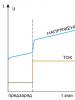
When studying the starting characteristics of starter electric motors, it was revealed that when voltage is applied to the electric motor, a reverse current pulse with a voltage of more than 2000 volts appears. The insulation of electric motor windings may fail and result in interturn breakdown. Sparking of the collector at high starting currents leads to burnout of the collector plates. You can avoid breakdown and an emergency situation when starting an electric motor by using the method of accelerating speed over time.
The starting current in this circuit is reduced to an acceptable value from 220 amperes to 20. Soft start conditions are created by a double current level - the first is created by the regulation characteristic of the field-effect transistor for a time of 0-10 ms, the second - by the contacts of the starting relay from 10 to 60 ms. The current during the starting mode increases almost linearly, which does not lead to destruction of the electrical part of the electric motor.
After pressing the “Start” button, the field-effect transistor is opened by applying voltage from the battery GB1 to the gate through resistor R1. A circuit parallel to the gate of the transistor and the minus of the battery protects the transistor and slightly increases the turn-on time from 0.02 to 1 ms, depending on the values of resistors R1, R2 and capacitor C1 - it supplies power to the starting motor M1 with increasing voltage. The electric motor will accelerate to rated speed, at the end of this process the powerful contacts K1.1 of relay K1 will close, the current through the field-effect transistor will stop, and the operating current of the electric motor will not create sparking of the contacts, since the acceleration mode has been completed.
Opening the “Start” circuit will lead to the opening of circuit K1.1 and de-energizing the electric motor, with the current decreasing exponentially.
A zener diode is introduced into the gate circuit of the field-effect transistor in the circuit to protect against exceeding the threshold voltage; in the source circuit of the transistor, in parallel with the starting electric motor, a circuit is connected to suppress the pulse voltage of reverse polarity - diode VD2 and capacitor C2.
The winding of relay K1 is protected from reverse polarity pulses by a bipolar LED HL1 with a discharge resistor R4; resistor R3 limits the supply current to the winding circuit and reduces its heating during prolonged operation. Diode VD3 eliminates the penetration of impulse noise into the power circuit.
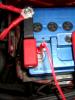
There are no scarce radio components in the circuit: field-effect transistors are installed for a total operating current of 212 amperes. Resistors type MLT-0.25, R3 for one watt. Diodes VD2, VD3 pulse type. Automotive relay - type MG16566DX for a contact current of 30 amperes and a voltage of 12 volts, the turn-on voltage of such a relay is 7 volts, the release voltage is 3.5 volts. We will replace the HL1 LED with KIPD 45B -2 or KIPD 23 A1-K, start button type KM 1-1. The design used an Italian-made starter motor; research was also carried out on other types of electric motors with power from 10 to 300 watts.
The structure is assembled in a housing measuring 110 * 35 * 55 and is fixed next to the starter, the start button is installed in a place convenient for turning on and is connected by a multi-core insulated wire with a cross-section of 0.5 mm. The field-effect transistors are secured with a common bolt to the radiator.
The LED can be used as a start indicator or left on the board.

The power supply circuits of the electric motor must be made with stranded wire with a cross-section of at least 10 mm and as short in length as possible to reduce voltage losses.
The circuit was tested on a bench with the specified 250-watt motor; for reliability, install two field switches in parallel, securing them on both sides of the radiator, the starting current can then reach 220 amperes. A current of 130 Amps is taken from the battery by the starter of the Zhiguli VAZ 2107.
List of radioelements
| Designation | Type | Denomination | Quantity | Note | Shop | My notepad |
|---|---|---|---|---|---|---|
| VT1 | MOSFET transistor | IRL2505L | 1 | To notepad | ||
| VD1 | Zener diode | KS818E | 1 | To notepad | ||
| VD2, VD3 | Rectifier diode | 1N4003 | 2 | To notepad | ||
| HL1 | Light-emitting diode | L-57EGW | 1 | To notepad | ||
| C1 | Capacitor | 0.1 µF | 1 | To notepad | ||
| C2 | Electrolytic capacitor | 100 µF | 1 | To notepad | ||
| R1 | Resistor | 120 kOhm | 1 | To notepad | ||
| R2 | Resistor | 75 kOhm | 1 | To notepad | ||
| R3 | Resistor | 1 ohm | 1 | To notepad | ||
| R4 | Resistor | 3.3 kOhm | 1 |
Soft starting of an electric motor has recently been used more and more often. Its areas of application are varied and numerous. These are industry, electric transport, utilities and agriculture. The use of such devices can significantly reduce starting loads on the electric motor and actuators, thereby extending their service life.
Starting currents
Starting currents reach values 7...10 times higher than in operating mode. This leads to a “sag” of voltage in the supply network, which negatively affects not only the operation of other consumers, but also the engine itself. The start-up time is delayed, which can lead to overheating of the windings and gradual destruction of their insulation. This contributes to premature failure of the electric motor.
Soft start devices can significantly reduce the starting load on the electric motor and the electrical network, which is especially important in rural areas or when the engine is powered from an autonomous power plant.
Overload of actuators
When the engine starts, the torque on its shaft is very unstable and exceeds the rated value by more than five times. Therefore, the starting loads of the actuators are also increased compared to operation in steady state and can reach up to 500 percent. Instability of the starting torque leads to shock loads on the gear teeth, shearing of keys and sometimes even twisting of the shafts.
Electric motor soft start devices significantly reduce starting loads on the mechanism: the gaps between the gear teeth are smoothly selected, which prevents their breakage. Belt drives also smoothly tension the drive belts, which reduces wear on the mechanisms.
In addition to a smooth start, the smooth braking mode has a beneficial effect on the operation of mechanisms. If the engine drives the pump, then smooth braking avoids water hammer when the unit is turned off.
Industrial soft starters
Currently produced by many companies, for example Siemens, Danfoss, Schneider Electric. Such devices have many functions that are user programmable. These are acceleration time, deceleration time, overload protection and many other additional functions.
With all the advantages, branded devices have one drawback - a fairly high price. However, you can create such a device yourself. At the same time, its cost will be small.
Soft start device based on KR1182PM1 microcircuit
The story was about specialized chip KR1182PM1, representing the phase power regulator. Typical circuits for switching it on, soft start devices for incandescent lamps, and simply load power regulators were considered. Based on this microcircuit, it is possible to create a fairly simple soft-start device for a three-phase electric motor. The device diagram is shown in Figure 1.
Figure 1. Scheme of the motor soft start device.
A soft start is carried out by gradually increasing the voltage on the motor windings from zero to the nominal value. This is achieved by increasing the opening angle of the thyristor switches over a time called the startup time.
Description of the circuit
The design uses a three-phase electric motor 50 Hz, 380 V. The star-connected motor windings are connected to the output circuits indicated in the diagram as L1, L2, L3. The center point of the star is connected to the network neutral (N).
The output switches are made on thyristors connected back-to-back - in parallel. The design uses imported 40TPS12 type thyristors. At a low cost, they have a fairly large current - up to 35 A, and their reverse voltage is 1200 V. In addition to them, the keys contain several more elements. Their purpose is as follows: damping RC circuits connected in parallel with the thyristors prevent false switching on of the latter (in the diagram these are R8C11, R9C12, R10C13), and with the help of varistors RU1...RU3 switching noise is absorbed, the amplitude of which exceeds 500 V.
DA1...DA3 microcircuits of type KR1182PM1 are used as control nodes for output switches. These microcircuits were discussed in some detail in. Capacitors C5...C10 inside the microcircuit form a sawtooth voltage, which is synchronized with the network voltage. The thyristor control signals in the microcircuit are generated by comparing the sawtooth voltage with the voltage between microcircuit pins 3 and 6.
To power relays K1…K3, the device has a power supply, which consists of only a few elements. This is transformer T1, rectifier bridge VD1, smoothing capacitor C4. At the output of the rectifier, an integrated stabilizer DA4 type 7812 is installed, providing an output voltage of 12 V, and protection against short circuits and overloads at the output.
Description of the operation of the soft starter for electric motors
Mains voltage is supplied to the circuit when power switch Q1 is closed. However, the engine does not start yet. This happens because the windings of relay K1...K3 are still de-energized, and their normally closed contacts bypass pins 3 and 6 of microcircuits DA1...DA3 through resistors R1...R3. This circumstance prevents capacitors C1...C3 from charging, so the microcircuit does not generate control pulses.
Putting the device into operation
When the toggle switch SA1 is closed, the 12 V voltage turns on relay K1…K3. Their normally closed contacts open, which makes it possible to charge capacitors C1...C3 from internal current generators. Along with the increase in voltage on these capacitors, the opening angle of the thyristors also increases. This achieves a smooth increase in voltage on the motor windings. When the capacitors are fully charged, the switching angle of the thyristors will reach its maximum value, and the rotation speed of the electric motor will reach the rated speed.
Engine shutdown, smooth braking
To turn off the engine, open switch SA1. This will turn off relay K1...K3. They are normal - the closed contacts will close, which will lead to the discharge of capacitors C1...C3 through resistors R1...R3. The discharge of the capacitors will last for several seconds, during which time the engine will stop.
When starting the engine, significant currents can flow in the neutral wire. This happens because during smooth acceleration the currents in the motor windings are non-sinusoidal, but there is no need to be particularly afraid of this: the starting process is quite short-lived. In steady-state mode, this current will be much less (no more than ten percent of the phase current in the nominal mode), which is due only to the technological dispersion of the winding parameters and the “misalignment” of the phases. It is no longer possible to get rid of these phenomena.
Details and design
To assemble the device, the following parts are required:
Transformer with a power of no more than 15 W, with an output winding voltage of 15...17 V.
Relays K1...K3 are suitable for any coil voltage of 12 V, having a normally closed or switching contact, for example TRU-12VDC-SB-SL.
Capacitors C11…C13 type K73-17 for an operating voltage of at least 600 V.
The device is made on a printed circuit board. The assembled device should be placed in a plastic case of suitable dimensions, on the front panel of which switch SA1 and LEDs HL1 and HL2 should be placed.
Motor connection
The connection between switch Q1 and the motor is made with wires whose cross-section corresponds to the power of the latter. The neutral wire is made of the same wire as the phase wires. With the part ratings indicated in the diagram, it is possible to connect motors with a power of up to four kilowatts.
If you plan to use a motor with a power of no more than one and a half kilowatts, and the start-up frequency will not exceed 10...15 per hour, then the power dissipated by the thyristor switches is insignificant, so radiators can not be installed.
If you plan to use a more powerful engine or the starts will be more frequent, you will need to install thyristors on radiators made of aluminum strip. If the radiator is supposed to be used as a common one, then the thyristors should be isolated from it using mica spacers. To improve cooling conditions, you can use heat-conducting paste KPT-8.
Checking and setting up the device
Before switching on, first of all, you should check the installation for compliance with the circuit diagram. This is the basic rule, and you cannot deviate from it. After all, neglecting this check can lead to a bunch of charred parts, and for a long time discourage you from doing “experiments with electricity.” The errors found should be eliminated, because after all, this circuit is powered from the network, and it is not to be trifled with. And even after this check, it is still too early to connect the engine.
First, instead of the engine, you should connect three identical incandescent lamps with a power of 60...100 W. During testing, it is necessary to ensure that the lamps “ignite” evenly.
The uneven turn-on time is due to the scatter in the capacitances of capacitors C1...C3, which have a significant tolerance on capacitance. Therefore, it is better to immediately select them using the device before installation, at least with an accuracy of up to ten percent.
The shutdown time is also determined by the resistance of resistors R1…R3. With their help you can adjust the shutdown time. These settings should be made if the spread in the on-off time in different phases exceeds 30 percent.
The engine can be connected only after the above checks have passed normally, not to say even perfectly.
What else can be added to the design?
It has already been said above that such devices are currently produced by different companies. Of course, it’s impossible to replicate all the functions of branded devices in such a homemade device, but you can still probably copy one.
We are talking about the so-called. Its purpose is as follows: after the engine has reached its rated speed, the contactor simply bridges the thyristor switches with its contacts. The current flows through them, bypassing the thyristors. This design is often called a bypass (from the English bypass - bypass). For such an improvement, additional elements will have to be introduced into the control unit.
Boris Aladyshkin