Assemble a reference frequency generator at 459 MHz. Circuits of high frequency (HF) generators. The generator consists of circuits
Low frequency generator circuit.
A low-frequency generator is one of the most necessary devices in an amateur radio laboratory. With its help, you can set up various amplifiers, measure the frequency response, and conduct experiments. An LF generator can be a source of LF signal necessary for the operation of other devices (measuring bridges, modulators, etc.).
The schematic diagram of the generator is shown in Figure 1. The circuit consists of a low-frequency sinusoidal generator on operational amplifier A1 and an output divider on resistors R6, R12, R13, R14.
The sine wave generator circuit is traditional. The operational amplifier, with the help of positive feedback (C1-C3, R3, R4, R5, C4-C6) made according to the Winn bridge circuit, is switched to generation mode. Excessive depth of positive feedback, leading to distortion of the output sinusoidal signal, is compensated by negative feedback R1-R2. Moreover, R1 is tuning, so that with its help it is possible to set the feedback value such that at the output of the operational amplifier there is an undistorted sinusoidal signal of the greatest amplitude.
Incandescent lamp H1 is switched on at the output of the op-amp in its feedback circuit. Together with resistor R16, the lamp forms a voltage divider, the division coefficient of which depends on the current flowing through it (lamp H1 acts as a thermistor, increasing its resistance from heating caused by the flowing current).
The frequency is set by two controls - switch S1 to select one of three subranges “20-200 Hz”, “200-2000 Hz” and “2000-20000 Hz”. In reality, the ranges are slightly wider and partially overlap each other. Smooth frequency adjustment is made by dual variable resistor R5. It is desirable that the resistor has a linear law of change in resistance. The resistances and laws of change of the components of R5 must be strictly the same, therefore, the use of homemade dual resistors (made from two single ones) is unacceptable. The nonlinear distortion coefficient of the sinusoidal signal greatly depends on the accuracy of the equality of resistances R5.
On the axis of the variable resistor there is a knob with an arrow (like on the instrument switches) and a simple scale for setting the frequency. To accurately set the frequency, it is best to use a digital frequency meter.
The output voltage is smoothly regulated by variable resistor R6. This resistor supplies low-frequency voltage to the output. You can lower the set value by 10 and 100 times using an attenuator on resistors R12-R14.
The maximum output voltage of the low-frequency generator is 1.0V.
It is most convenient to control the output voltage using a low-frequency millivoltmeter, making corrections for the value of the attenuator on resistors R12-R14.
Turn off the generator with a two-way toggle switch S2, which disconnects the generator from a bipolar voltage source of ±10V.

Most of the parts are located on the printed circuit board. All resistor regulators, switches and connectors are located on the front panel. Many parts are mounted on their terminals.
Switch S1 is a three-way, three-position switch. Only two directions are used. Switch S2 is a two-way toggle switch. All connectors are “Asia” type coaxial connectors from video equipment. Chokes L1 and L2 are from color modules of old USST TVs (you can use any chokes with an inductance of at least 30 μH). The H1 incandescent lamp is an indicator lamp, with flexible wire leads (similar to an LED), with a voltage of 6.3V and then 20 tA. You can use another lamp with a voltage of 2.5-13.5V and a current of no more than 0.1 A.
It is advisable to set up the generator using a frequency meter and an oscilloscope. In this case, by adjusting resistor R1, a maximum and undistorted alternating sinusoidal voltage is achieved at the output of the generator, over the entire frequency range (this usually corresponds to an output alternating voltage of 1V). Then, by more precise selection of R4 and R3 (these resistances must be the same), the frequency tuning ranges are set. If insufficiently accurate capacitors C1-C6 are used, it may be necessary to select them or connect “additional” capacitors in parallel with them.
Ivanov A.
Literature:
1. Ovechkin M. Low-frequency measuring complex, railway. Radio No. 4, 1980.
Radioconstructor 08-2016
Download: Low-frequency generator for amateur radio laboratory
If you find broken links, you can leave a comment, and the links will be restored as soon as possible.
We assemble a simple function generator for the laboratory of a novice radio amateur
Good afternoon, dear radio amateurs! Welcome to the website ““
We assemble a signal generator - a function generator. Part 3.
Good afternoon, dear radio amateurs! At today's lesson in Beginning radio amateur school we'll finish collecting function generator. Today we will assemble a printed circuit board, solder all the attached parts, check the functionality of the generator and configure it using a special program.
And so, I present to you the final version of my printed circuit board made in the program that we looked at in the second lesson - Sprint Layout:
If you were unable to make your own version of the board (something didn’t work out, or you were just lazy, unfortunately), then you can use my “masterpiece”. The board is 9x5.5 cm in size and contains two jumpers (two blue lines). Here you can download this version of the board in Sprint Layout format^
(63.6 KiB, 3,488 hits)
After using laser ironing technology and etching, the result was the following workpiece:

The tracks on this board are made with a width of 0.8 mm, almost all pads are 1.5 mm in diameter, and almost all holes are made with a 0.7 mm drill. I think that it will not be very difficult for you to understand this board, and also, depending on the parts used (especially the trimmers), make your own changes. I want to say right away that this board has been tested and if the parts are soldered correctly, the circuit starts working immediately.
A little about the functionality and beauty of the board. When you pick up a factory-made board, you probably noticed how conveniently it is prepared for soldering parts - so-called “silk-screen printing” is applied in white on both the top and bottom, on which the names of the parts and their locations are immediately visible, which makes life very easy when soldering radioelements. Seeing the seat of the radio element, you will never be mistaken in which holes to insert it into, all you have to do is look at the diagram, select the desired part, insert it and solder it. Therefore, today we will make a board close to the factory one, i.e. Let's apply silk-screen printing to the layer from the parts side. The only thing is that this “silk-screen printing” will be black. The process is very simple. If, for example, we use the Sprint Layout program, then when printing we select layer K1 (the layer on the parts side), print it as for the board itself (but only in mirror image), put a print on the side of the board where there is no foil (with sides of the parts), center it (and the pattern is fairly visible in the light of the etched board) and using the LUT method we transfer the toner to the PCB. The process is the same as when transferring toner to copper, and we admire the result:

After drilling the holes, you will actually see the layout of the parts on the board. And the most important thing is that this is not only for the beauty of the board (although, as I already said, a beautiful board is the key to good and long-term operation of the circuit you have assembled), but most importantly, to facilitate further soldering of the circuit. The ten minutes spent on applying “silk-screen printing” significantly pays off in time when assembling the circuit. Some radio amateurs, after preparing the board for soldering and applying such “silk-screen printing,” cover the layer on the parts side with varnish, thereby protecting the “silk-screen printing” from being erased. I would like to note that the toner on the PCB adheres very well, and after soldering the parts you will have to remove the remaining rosin from the board with a solvent. If solvent gets on the “silk-screen printing” coated with varnish, it leads to the appearance of a white coating, when removed, the “silk-screen printing” itself comes off (this is clearly visible in the photograph, this is exactly what I did), therefore, I believe that it is not necessary to use varnish. By the way, all the inscriptions and contours of parts are made with a line thickness of 0.2 mm, and as you can see, all this is perfectly transferred to the textolite.
And this is what my board looks like (without jumpers and attachments):

This board would have looked much better if I hadn't varnished it. But you can, as always, experiment and, of course, do better. In addition, I have two C4 capacitors installed on the board; I didn’t have the required value (0.22 μF), so I replaced it with two 0.1 μF capacitors connecting them in parallel.
Let's continue. After we have soldered all the parts onto the board, we solder two jumpers and solder resistors R7 and R10 and switch S2 using sections of mounting wires. We do not solder switch S1 yet, but make a jumper from a wire, connecting pins 10 of the ICL8038 microcircuit and capacitor C3 (i.e., we connect the range 0.7 - 7 kHz), supply power from our (I hope assembled) laboratory power supply to the inputs of microcircuit stabilizers about 15 volts DC voltage
Now we are ready to test and configure our generator. How to check the functionality of the generator. Very simple. We solder to the outputs X1 (1:1) and “common” any ordinary or piezoceramic speaker (for example, from a Chinese clock in an alarm clock). When the power is connected, we will hear a beep. When changing resistance R10, we will hear how the tone of the output signal changes, and when changing resistance R7, we will hear how the volume of the signal changes. If you don’t have this, then the only reason is improper soldering of the radio elements. Be sure to go through the scheme again, eliminate the shortcomings and everything will be ok!
We will assume that we have passed this stage of generator manufacturing. If something doesn’t work out, or it works out but not right, be sure to ask your questions in the comments or on the forum. Together we will solve any problem.
Let's continue. This is what the board looks like ready for configuration:

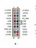
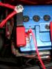
What we see in this picture. Power supply – black “crocodile” to the common wire, red “crocodile” to the positive input of the stabilizer, yellow “crocodile” - to the negative input of the negative voltage stabilizer. Soldered variable resistances R7 and R10, as well as switch S2. From our laboratory power supply (this is where the bipolar power supply comes in handy), we supply the circuit with a voltage of about 15-16 volts, so that the 12-volt microcircuit stabilizers work normally.
Having connected power to the inputs of the stabilizers (15-16 volts), use a tester to check the voltage at the outputs of the stabilizers (±12 volts). Depending on the voltage stabilizers used, the voltage will differ from ± 12 volts, but is close to it. If your voltages at the outputs of the stabilizers are absurd (do not correspond to what is needed), then there is only one reason - poor contact with ground. The most interesting thing is that even the lack of reliable contact with the “ground” does not interfere with the operation of the generator on the speaker.
Well, now we just need to configure our generator. We will carry out the setup using a special program - virtual oscilloscope. On the Internet you can find many programs that simulate the operation of an oscilloscope on a computer screen. Especially for this lesson, I checked many such programs and chose one, which, it seems to me, simulates an oscilloscope the best - Virtins Multi-Instrument. This program includes several subprograms - an oscilloscope, a frequency meter, a spectrum analyzer, a generator, and in addition there is a Russian interface:

Here you can download this program:
(41.7 MiB, 5,238 hits)
The program is easy to use, and to configure our generator you only need minimal knowledge of its functions:

In order to configure our generator, we need to connect to the computer via a sound card. You can connect through the line input (not all computers have it) or to the microphone connector (available on all computers). To do this, we need to take some old, unnecessary headphones from a phone or other device, with a plug with a diameter of 3.5 mm, and disassemble them. After disassembly, solder two wires to the plug - as shown in the photo:

After this, solder the white wire to ground and the red wire to pin X2 (1:10). We set the R7 signal level control to the minimum position (be sure to not burn the sound card) and connect the plug to the computer. We launch the program, and in the working window we will see two running programs - an oscilloscope and a spectrum analyzer. Turn off the spectrum analyzer, select “multimeter” on the top panel and launch it. A window will appear that will show the frequency of our signal. Using resistor R10 we set the frequency to about 1 kHz, set switch S2 to position “1” (sinusoidal signal). And then, using trimming resistors R2, R4 and R5, we configure our generator. First, the shape of a sinusoidal signal with resistors R5 and R4, achieving a sine wave shape on the screen, and then, switching S2 to position “3” (rectangular signal), using resistor R2 we achieve signal symmetry. You can see what it really looks like in this short video:
After completing the steps and setting up the generator, we solder switch S1 to it (after removing the jumper) and assemble the entire structure in a ready-made or homemade (see lesson on assembling a power supply) case.
Let's assume that we have successfully dealt with everything, and a new device has appeared in our amateur radio equipment - function generator . We will not equip it with a frequency meter yet (there is no suitable circuit) but will use it in this form, given that we can set the frequency we need using the program Virtins Multi-Instrument. We will assemble a frequency meter for the generator on a microcontroller, in the “Microcontrollers” section.
Our next stage in the knowledge and practical implementation of amateur radio devices will be the assembly of a light-and-music installation using LEDs.
When repeating this design, there was a case when it was not possible to achieve the correct shape of rectangular pulses. It is difficult to say why such a problem arose, perhaps because of the way the chip works. Solving the problem is very easy. To do this, you need to use a Schmitt trigger on the K561(KR1561)TL1 chip according to the diagram below. This circuit allows you to convert voltage of any shape into rectangular pulses with a very good shape. The circuit is connected to the gap in the conductor coming from pin 9 of the microcircuit, instead of capacitor C6. 
Capable of simultaneously generating square and sawtooth waveforms, it usually consists of two parts (Fig. 36.1):
♦ non-inverting Schmitt trigger on the DA1 chip;
♦ integrator on the DA2 chip.
At C 1=4.7 nF, the generation frequency is 30 kHz, at 0=47 nF -
20 Hz. The generator supply voltage can vary between 4.5-18 V.
Considering the high relevance of function generators, specialized microcircuits for such generators were created. An example is the ICL8038 from Harris Semiconductor.

Supply voltage ±(5-15) V for bipolar supply or 10-30 V for unipolar supply. The current consumed by the microcircuit does not exceed 20 mA (nominal - 12 mA) at a supply voltage of ±10 V. The amplitude of the triangular output voltage at a load resistance of 100 kOhm reaches 1/3 of the supply voltage, for a sinusoidal signal - up to 0.22 of the supply voltage .
Options for connecting external elements for adjusting the operating mode of the ICL8038 microcircuit are shown in Fig. 36.6.
When using the ICL8038 chip (Fig. 36.7), it is convenient
Rice. 36.6. Options for connecting resistive elements to the ICL8038 chip

Rice. 36.7. Option to include the ICL8038 chip with frequency modulation of the generated signals

carry out frequency modulation of the generated signals. Using this feature of the microcircuit, it is easy to create signals of rectangular, triangular and sinusoidal shapes, simultaneously controlled by the level of external voltage.
To reduce distortion of a sinusoidal signal, the adjustments provided for in the circuit design shown in Fig. are used. 36.8.

Rice. 36.8. inclusion of the ICL8038 microcircuit with minimization of sinusoidal signal distortion
In order to increase the load capacity of the generator, use the circuit shown in Fig. 36.9. A conventional buffer stage is used, which can be used for each of the outputs. load is determined by the choice
op-amp microcircuits; for the given load case should not be less than 1 kOhm.

Rice. 36.9. on the ICL8038 chip with increased load capacity for a sinusoidal signal

Rice. 36L0. on the ICL8038 chip with frequency adjustment from 20 Hz to 20 kHz
A practical wide-range, covering the entire range of audio frequencies, is shown in Fig. 36.10. Potentiometer R7 minimizes distortion of the sinusoidal signal. R3 is designed to adjust the pulse/pause ratio (or symmetry) of the generated signals. Potentiometer R10 regulates the frequency of the generated signals.
Additive triangular signal conditioner
Triangular-shaped electrical signals are usually obtained using charge-discharge processes in RC circuits. The works describe and analyze the principle of generating triangular signals by antiphase addition of sinusoidal signals rectified using full-wave rectifiers, shifted between each other by an angle of 90°. Below is a practical implementation of a frequency-tunable triangular signal generator using this synthesis principle.
DA1-DA3 collects LR-signals of a sinusoidal shape, from the outputs of which signals shifted in phase by an angle of 90° are removed (points A and B). These signals are fed to the inputs of two precision rectifiers, made DA4, DA5 and DA6, DA7, respectively. The signals from the outputs of the rectifiers (points C and D) are mixed at the resistive adder-voltage divider R13, R15, R16 (point E). The output signal (point E) has a triangular shape with a deviation from linearity of up to 3%.
The operating frequency of the generator is determined by the ratings of the frequency-setting circuits - inductors LI, L2, dual potentiometer R9, R10 and resistors R7, R8. For the indicated ratings, the tuning frequency range is 3300-4000 Hz.
You can change the frequency range of operation stepwise by switching inductors LI, L2. When expanding the tuning range by further changing the ratio of elements

Rice. 36.11. capacitive tunable triangular signal generator
R7/R9=R8/R10 the pronounced dependence of the output signal amplitude on frequency becomes noticeable. To eliminate this drawback, it is necessary either to narrow the tuning range of the generator, or to use intermediate amplifiers with automatic gain control.
Inverse construction
When creating functional generators, rectangular pulses are traditionally used, to the output of which a triangular voltage former based on charge-discharge processes is connected. Then the triangular signal is converted into something similar to a sinusoidal one, isolating the first harmonic from it. The disadvantages of such circuit solutions are obvious: this is a pronounced nonlinearity of charge-discharge processes, especially noticeable when adjusting the frequency of the generator, and noticeable distortion of the sinusoidal signal as a result of poor-quality filtering of higher harmonics of a complex signal.
S.I. Semenova - precision full-wave rectifiers (microcircuits DA4, DA5 and DA9, DA10), the output signals of which are added in antiphase, thereby forming a triangular signal. The triangular signal is then fed to the circuit for generating rectangular bipolar pulses (chips DA6-DA8).
Signal diagrams at various points of the device are shown in Fig. 36.12.
Operates in the frequency range: for sinusoidal signals - 50-500 Hz, for triangular and rectangular signals (with doubling the original frequency) - 100-1000 Hz. The operating frequency is smoothly changed by adjusting the dual potentiometer R9, R10. Stepwise switching of the range of generated frequencies down to subhertz can be achieved by switching frequency-setting capacitors C2 and SZ. Thus, when the capacitances of capacitors C2 and SZ are reduced by 10 times, i.e. to 3.3 nF, the range of generated frequencies is 1000-10000 Hz for sawtooth and square wave signals; sinusoidal - 500-5000 Hz. 
Shustov M. A., Circuitry. 500 devices on analog chips. - St. Petersburg: Science and Technology, 2013. -352 p.
Simple analog function generator (0.1 Hz - 8 MHz). The article is reprinted from the site.
The MAX038 chip is deservedly popular among radio amateurs, on the basis of which it is possible to assemble a simple function generator covering a frequency band of 0.1 Hz - 20 MHz. Purchasing the MAX038 microcircuit has become easier than ever, as indicated here. The MAX038 clones that have appeared have very modest parameters in comparison with it. So, the ICL8038 has a maximum operating frequency of 300 kHz, and the XR2206 has a maximum operating frequency of 1 MHz. Circuits of simple analog function generators found in amateur radio literature also have a maximum frequency of several tens, and very rarely, hundreds of kHz.
For your attention, we have proposed a circuit of an analog functional generator that generates signals of sinusoidal, rectangular, triangular shape and operates in the frequency range from 0.1 Hz to 8 MHz.
Front view:
Back view:

The generator has the following parameters:
amplitude of output signals:
sinusoidal……………………………1.4 V;
rectangular……………………………..2.0 V;
triangular………………………………...2.0 V;
frequency ranges:
0.1…1 Hz;
1…10 Hz;
10…100 Hz;
100…1000 Hz;
1…10 kHz;
10…100 kHz;
100…1000 kHz;
1…10 MHz;
supply voltage………………………….220 V, 50 Hz.
The basis for the developed circuit of the function generator given below was taken from:

The generator is made according to the classical scheme: integrator + comparator, only assembled on high-frequency components.
The integrator is assembled on the DA1 AD8038AR op-amp, which has a bandwidth of 350 MHz and an output voltage slew rate of 425 V/μs. A comparator is made on DD1.1, DD1.2. Rectangular pulses from the output of the comparator (pin 6 DD1.2) are supplied to the inverting input of the integrator. An emitter follower is made on VT1, from which triangular-shaped pulses that control the comparator are removed. Switch SA1 selects the required frequency range, potentiometer R1 serves to smoothly adjust the frequency. The trimmer resistor R15 sets the operating mode of the generator and regulates the amplitude of the triangular voltage. Trimmer resistor R17 regulates the constant component of the triangular voltage. From the emitter VT1, a triangular voltage is supplied to the switch SA2 and to the sinusoidal voltage driver, made at VT2, VD1, VD2. Trimmer resistor R6 sets the minimum distortion of the sinusoid, and trimmer resistor R12 regulates the symmetry of the sinusoidal voltage. In order to reduce the harmonic distortion, the peaks of the triangular signal are limited to the circuits VD3, R9, C14, C16 and VD4, R10, C15, C17. Rectangular pulses are taken from buffer DD1.4. The signal selected by switch SA2 is fed to potentiometer R19 (amplitude), and from it to the output amplifier DA5, made on the AD8038AR. The elements R24, R25, SA3 have an output voltage attenuator of 1:1 / 1:10.
To power the generator, a classic transformer source with linear stabilizers generating voltages of +5V, ±6V and ±3V is used.
To indicate the frequency of the generator, a part of the circuit from a ready-made frequency meter was used, taken from:

Transistor VT3 is used as a rectangular pulse shaper amplifier, from the output of which the signal is sent to the input of the DD2 PIC16F84A microcontroller. The MK is clocked from the ZQ1 quartz resonator at 4 MHz. Using the SB1 button, you select the low-order price of 10, 1 or 0.1 Hz and the corresponding measurement time of 0.1, 1 and 10 seconds on the ring. The indicator used is WH1602D-TMI-CT with white symbols on a blue background. True, the viewing angle of this indicator turned out to be 6:00, which did not correspond to its installation in a case with a viewing angle of 12:00. But this trouble was eliminated, as will be described below. Resistor R31 sets the backlight current, and resistor R28 regulates the optimal contrast. It should be noted that the program for the MK was written by the author for indicators such as DV-16210, DV-16230, DV-16236, DV-16244, DV-16252 from DataVision, whose initialization procedure apparently does not fit the WH1602 indicators from WinStar . As a result, after assembling the frequency meter, nothing was displayed on the indicator. There were no other small-sized indicators on sale at that time, so we had to make changes to the source code of the frequency meter program. Along the way, during the experiments, such a combination was identified in the initialization procedure, in which a two-line display with a viewing angle of 6:00 became a single-line display, and quite comfortably readable at a viewing angle of 12:00. The hints about the operating mode of the frequency meter displayed in the bottom line are no longer visible, but they are not particularly needed, because Additional functions of this frequency meter are not used.
Structurally, the functional generator is made on a printed circuit board made of single-sided foil fiberglass with dimensions of 110x133 mm, designed for a standard Z4 plastic case. The indicator is installed vertically on two corners of the chamber. It is connected to the main board using a cable with an IDC-16 connector. To connect high-frequency circuits, a thin shielded cable is used in the circuit. Here is a photo of the generator with the top housing cover removed:

After turning on the generator for the first time, it is necessary to check the supply voltages, and also set the voltage at the DA7 LM337L output to -3V using trimming resistor R29. Resistor R28 sets the optimal contrast of the indicator. To configure the generator, you need to connect an oscilloscope to its output, set switch SA3 to the 1:1 position, SA2 to the position corresponding to the triangular voltage, SA1 to the 100…1000 Hz position. Resistor R15 achieves stable signal generation. By moving the slider of resistor R1 to the lower position in the diagram, using trimming resistor R17, the triangular signal is symmetrical relative to zero. Next, switch SA2 must be moved to the position corresponding to the sinusoidal shape of the output signal, and using trimming resistors R12 and R6, respectively, achieve symmetry and minimal distortion of the sinusoid.
Here's what we ended up with:
Square wave 1 MHz: Square wave 4 MHz: Triangle 1 MHz:


Triangle 1 MHz: Sine 8 MHz:


It should be noted that at frequencies above 4 MHz, distortion begins to be observed on triangle and rectangular signals due to insufficient bandwidth of the output amplifier. If desired, this drawback can be easily eliminated by moving the output stage amplifier DA5 to the circuit from the source VT2 to SA2, i.e. use it as an amplifier for a sinusoidal signal, and instead of an output amplifier, use a repeater on another AD8038AR op-amp, respectively recalculating the resistance of the triangular (R18, R36) and rectangular (R21, R35) signal dividers to a lower division factor.
Files:
Literature:
1) Wide-range function generator. A.Ishutinov. Radio No. 1/1987
2) Economical multifunctional frequency meter. A. Sharypov. Radio No. 10-2002.
I wanted to create a function generator that generates audio signals for effects/amp testing; as well as TTL clock signals for digital circuits. Since new function generators usually cost around £20, I figured I could make one myself.
For this project, I used the XR-2206 IC to generate the oscillating signal. The integrated circuit can create a signal in the form of sine and triangular pulses with a given amplitude and frequency, as well as a TTL synchronization signal at a voltage of 5 V. The frequency range ranges from 20 Hz to 300 kHz - so this function generator will cover the entire human audible frequency range.
The integrated circuit has inputs to control the frequencies of all signals as well as the amplitude of the sine/triangle signal.
Step 1: Component List
Basic components for a function generator
- (2x) 1uF electrolytic capacitors
- (1x) 100nF ceramic/polyester capacitor
- (1x) 10nF ceramic/polyester capacitor
- (1x) 1nF ceramic/polyester capacitor
- (1x) 10ohm resistor
- (2x) 1K resistors
- (1x) 3K resistor
- (2x) 5K resistors
- (1x) 10K resistor
- (1x) 30K resistor
- (2x) 10KΩ panel mount potentiometers
- (1x) 100KΩ panel mount potentiometer
- (2x) 25Kohm string resistors
- (1x) 4 rotary position switch
- (1x) single pole changeover switch
- (5x) 4mm banana jacks
- (1x) 16 pin DIL socket
- (1x) XR2206 Function Generator IC
- Device case
- Bread board
- Wires with stranded conductor
Additional components for optional power supply
- (1x) 15V AC transformer
- (1x) IEC power input
- (1x) double pole switch
- (1x) 1A fuse and holder
- (1x) 1A bridge rectifier or (4x) 1N4001 diodes
- (1x) 2200uF electrolytic capacitor
- (1x) 10uF electrolytic capacitor
- (1x) 100nF polyester capacitor
- (1x) 220ohm resistor
- (1x) 5mm LED with holder
- (1x) IC 7812 - voltage stabilizer
- Flexible wire for connecting power supply
Step 2: Electrical Diagram


For this project, a multi-function oscillator IC is used - this ensures a simple design, as well as a small number of components. I actually used two ICs that met the spec - Exar XR2206 and Maxim MAX038. In conclusion, I decided to use the XR2206 - this chip is easier and cheaper to purchase.
The frequency is adjusted by two potentiometers - one for coarse tuning and the other for fine tuning. It is important that you use good quality potentiometers for this purpose, otherwise it will be very difficult to set the exact frequency and it will fluctuate. Alternatively, you can replace the two variable resistors with a 10 turn, 100 kohm potentiometer for greater accuracy.
I didn't use a PCB for this project because I soldered as best I could, but you can see that the different components are located in different parts of the board. The power supply filter and voltage divider for amplitude control are located on the left, while the capacitors for the frequency range are located in the lower center. By dividing the wiring diagram into several subsections it is easier to develop the design of the printed circuit board.
This circuit is designed to operate from a unipolar 12 V DC power supply. A suitable power source is shown in the next step.
Step 3: Power Supply


**This part of the circuit includes operation with a high voltage alternating current source. If you are unsure about working with potentially lethal voltage levels, SKIP THIS PART OF THE PROJECT. Instead you can useA.C. power adapter. I am not responsible for any damage or injury that may occur while working on this project.**
I decided to use the internal power supply for the function generator so as not to have to look for AC power modules. This means that I don't have to recalibrate the function generator every time I start on a different supply voltage, since the transformer inside the case will always output the same voltage.
Make sure the 1A fuse breaks the live power supply conductor. If using a metal enclosure, make sure it is connected to the power supply grounding conductor. I placed all the power supply circuits on my own board away from the main power supply circuitry in order to simplify the design and reduce interference. Make sure that all live conductors are connected on the primary side of the transformer.
Step 4: Body


I placed all the electronic components in a plastic instrument case. I used the housing shown on the website http://www.evatron.com, although there are many similar options. I used a marker to mark the connectors and controls.
Step 5: Calibration


An oscilloscope is required to calibrate the function generator.
It is very important to properly calibrate the circuit in order to obtain a clean oscillatory signal at the output. Start by selecting the sine wave by turning off the sine/triangle switch. Set the frequency range to the second range, and the amplitude to maximum.
Connect an oscilloscope probe to the sine/triangle output and set your oscilloscope to AC coupled - the oscilloscope signal has a DC offset, in other words you won't see the full waveform on the screen.
Set the trim resistor to the middle position and adjust the offset of the trim resistor until the sine wave signal is clearly displayed on the oscilloscope. Using the distortion control device, continue to adjust the symmetry to further reduce distortion. You should get a pure sine wave similar to the one shown in the diagram.
A triangle waveform has a larger amplitude than a sine wave, so it will clip at full amplitude while a sine wave will not. This, unfortunately, is an internal defect in the circuit, but is not a major drawback since you can manually set the amplitude. The square wave signal is fixed at 5 V and does not need to be adjusted.
Step 6: Modifications and Updates

It is possible to make many changes to this project to tailor it to your specific requirements. It is also possible to increase the maximum frequency range by adding a 5th position to the rotary switch and connecting a 100 pF capacitance, similar to other connected components. This will raise the max. frequency up to 3 MHz (at this value it is only valid to use a square wave signal).
You can also use a rotary switch to select the waveform, but to obtain it you will need proper wiring, as well as replacing the sine/triangle switch.
I hope you find this project useful - it came in very handy when testing audio circuits.
List of radioelements
| Designation | Type | Denomination | Quantity | Note | Shop | My notepad | |
|---|---|---|---|---|---|---|---|
| Function generator | XR2206 | 1 | To notepad | ||||
| 1 µF | 2 | To notepad | |||||
| Electrolytic capacitor | 10 µF | 1 | To notepad | ||||
| Capacitor | 100 nF | 1 | ceramic/polyester | To notepad | |||
| Capacitor | 10 nF | 1 | ceramic/polyester | To notepad | |||
| Capacitor | 1 nF | 1 | ceramic/polyester | To notepad | |||
| Resistor | 10 ohm | 1 | To notepad | ||||
| Resistor | 1 kOhm | 2 | To notepad | ||||
| Resistor | 3 kOhm | 1 | To notepad | ||||
| Resistor | 5 kOhm | 2 | To notepad | ||||
| Resistor | 10 kOhm | 1 | To notepad | ||||
| Resistor | 30 kOhm | 1 | To notepad | ||||
| Variable resistor | 10 kOhm | 1 | To notepad | ||||
| Variable resistor | 100 kOhm | 1 | To notepad | ||||
| Trimmer resistor | 25 kOhm | 2 | To notepad | ||||
| Position switch | 1 | 4 rotary | To notepad | ||||
| Switch | 1 | single-pole changeover | To notepad | ||||
| 4mm banana sockets | 5 | To notepad | |||||
| DIL socket | 1 | 16 pin | To notepad | ||||
| Linear regulator | UA7812 | 1 | To notepad | ||||
| Rectifier diode | |||||||