We are remaking an old radio in a modern way. Remaking a car radio (improving the sound) Do-it-yourself amplifier from a radio
Car enthusiasts, as you know, prefer to listen to their favorite music in their cars quite loudly. However, standard radios cannot always maintain high-quality sound when the volume is increased. To avoid this, you can connect a radio amplifier and a subwoofer to the standard device.
Amplifier selection
Since the car only has 1-2 12 V batteries, it is necessary to calculate the audio connection to a low-power network. It is to this that the device is connected so that the voltage is increased to 100 V.
When choosing an amplifier for your radio, you need to pay attention to the following factors:
- unit of power - it is necessary that it corresponds to the values of other automotive equipment;
- rated power - should be slightly less than the power of standard acoustics for the highest quality sound;

- equality of load resistance on the amplifier and the system;
- l minimum frequency range – must be at least 20 Hz.
If you have a fairly modern car, then it may be equipped with a crossover - this is an auxiliary device that will ensure the operation of the amplifier in different modes. Typically, in such cars you can connect not one, but two amplifiers to the standard radio if desired. Most car owners give their preference to Pioneer devices.

Connection
Many car enthusiasts prefer to take care of their cars themselves, so they ask the question: “How to connect the amplifier to the radio with your own hands?”
Actually, it's not very difficult. The main thing is to follow a number of simple rules and follow the instructions.
First of all, you need to choose a place - it must be dry and have sufficient heat transfer. This is necessary in order to maintain the functionality of the device. Usually it is placed deep in the trunk.

Connecting the amplifier to the radio is as follows:
- Step 1. Laying the signal cable. Usually carried out under firmware to ensure its safety. The owner of the car chooses the route independently as it is convenient for him.
- Step 2. Laying additional cable. Carried out in conjunction with a signal cable. It is worth noting that they should not come into contact with live wires responsible for the on-board network.
- Step 3. Laying the power cable and installing the fuse. Powered by battery. In this case, the fuse must be placed as close to it as possible. You can lay the power cable close to the main wiring of the machine.
- Step 4. Connect the signal cable. Naturally, there are only 2 connectors to which it can be connected. Directly on a standard device this is the output - that is, Line-Out, and on the amplifier, accordingly, the input is Line-In.

- Step 5. Connecting an additional cable. There are also 2 connectors. On the radio it is B+Ant, and on the amplifier it is Remote. It is imperative to do this, because otherwise the system simply will not work.
- Step 6: Connect to speakers. If you have a bridge Pioneer, then it has 2 channels. They are connected respectively to the “plus” and “minus” of the speaker.
- Step 7: Installing the capacitor. A storage capacitor is a kind of stabilizer that serves as an auxiliary device for the car's network so that there are no problems with increasing load. It protects both the on-board network and the amplifier from voltage surges.
- Step 8. Setup. This stage is strictly individual for each device and depends on the amplifier itself, the radio and the presence of a subwoofer.

If an amplifier is not enough for a music lover, then there is another device to improve sound quality at high volumes - a subwoofer.
What types of subwoofers are there?
- Passive. Connect it to an additionally installed amplifier. However, experts do not recommend using it, since the filter present in its device removes some frequencies. To prevent this from happening, connect a separate device for the subwoofer.
- Active. It has a built-in amplifier, so the passive problem solves itself.

Connecting a subwoofer
- Step 1. Selecting and connecting the power cable. It is very important to make the right choice because it will directly affect the sound quality. There is a special table that allows you to select a cable that matches your device in terms of power. Experts recommend making two wirings at once - to the plus and minus, however, the minus is often attached to the body.
- Step 2: Install the fuse. This step will help you keep your subwoofer working if a power surge occurs. The fuse must be placed as close to the battery as possible. Moreover, its minimum power must be 40A, otherwise it simply will not perform its function.
- Step 3. Connect to the radio. There are two options here - with or without a special output on the standard radio:
- In the first case, everything is simple. The subwoofer output is specified in the instructions and is usually labeled Out.
- In the second case, you should connect the subwoofer through the speaker output, and use a filter.
- There is a special jack on the subwoofer itself to perform this step, labeled In.
- Step 4: Installing the capacitor. If you already have a capacitor installed and you can connect a subwoofer to it, then that's just great - you don't need to purchase an additional device. This step cannot be avoided - it is necessary to relieve the load on the on-board network. Therefore, if there is no capacitor, then you definitely need to purchase one. You can notice the effect of a subwoofer without a capacitor on it with the naked eye - the indicators on the dashboard will glow more dimly.

The choice of amplifier and subwoofer, as well as their connection, is a decision that every motorist must make independently. You can choose a high-quality and proven device, such as Pioneer, or something less reliable - it’s up to you. It’s always worth remembering that choosing an update and connecting it can directly affect the operation of your car - if you do something wrong, your dashboard may simply stop working, or the entire on-board network may malfunction. Therefore, if you are not sure that you can make the correct connection yourself, then it is better to entrust the work to professionals.
Car radio power amplifier chip
The car radio power amplifier chip was developed in 1998 by the world famous company Philips. The car radio power amplifier chip was intended to amplify the head unit.
Brief performance characteristics of the microcircuit
The data is given below:
- equipped with a built-in supply voltage converter;
- the voltage converter at a relatively low voltage allows you to create an output power of 70 W at a load of 4 ohms;
- the chip has a class B output power of about 18 W at a voltage of 14.4 V;
- The power supply of the internal circuit can be increased by increasing the switching on of the converter, which increases the output voltage.
Note. It is necessary to objectively understand that the voltage booster does not always function, but only when the output power crosses a certain limit. And this mode of operation was called N.
The microcircuit also contains a MODE output, which is capable of operating in three modes, namely:
- active mode ON;
- standby mode STD-BY;
- in silent MUTE state.
In its functional assets, the microcircuit also contains specialized integrated units for protection against:
- possible short circuit of conductors located at the output;
- short circuit caused by the intersection of a power wire with a positive charge and a common wire;
- temperature overheating in case of operating overload.
The TDA chip contains a dynamic distortion detection detector, which turns on automatically if distortion doses occur in the output signal.
This does not occur with the saturation effect:
- The input signal voltage increases, however, the output signal does not increase, continuing to be within the voltage limits created by the power amplifier.
This microcircuit is represented by film capacitors, namely:
- C3 – 0.1 µF;
- C4 – 2.2 µF;
- C7 and C8 – 3300 µF.
There are also X2 terminals, which are necessary to both turn the amplifier on and off.
Note. The MODE output can be artificially connected to the REMOTE output on the car radio, which in turn will create the possibility of remote control. In this case, immediately after starting the car radio, an output signal with a voltage of 12 will appear, which will actually drive the amplifier.
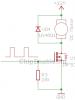
The TDA1562Q chip also has additional X3 terminals, which can, if necessary, be used as an indicator of the amplifier's emergency condition. For this purpose, it is enough to simply connect an LED to the X3 terminals.
Distinctive features of the TDA chip for a car radio amplifier
Here they are:
- Since the flange of the amplifier chip is connected directly to the common wire, there is no need for an insulating radiator gasket if the attachment point is a radiator.
Note. It is imperative to lubricate the fastenings with a specialized heat-conducting paste, otherwise this design will last a short period of time.
- Additionally, it will be necessary to tin all power paths.
Moments that motorists pay little attention to
As a rule, they are like this:
- You must always remember that over time, the internal wiring of the car radio (see) and its additional components deteriorate, which can cause interruptions in the operation of the amplifier;
- it is extremely important to effectively correlate the voltage created at the input with the one that should be obtained at the output;
- It is imperative that you carefully read the detailed illustrated diagram, which can easily be found on the Internet;
- An equally important point is the proper operation of the radiator, which must not only function, but function effectively; otherwise, the amplifier of the microcircuit will overheat and it will simply go out of its working state.
Distinctive advantages and disadvantages of choosing a TDA chip from Philips
| low market value | slight technological obsolescence |
| speed and ease of operation | lack of modern functionality |
| proper reliability and performance and the required degree of functionality | Difficulty combining with luxury car radios |
| wide range of compatibility with car radios | the need for annual inspection of all components |
| Availability of operating instructions on the Internet | |
| simplicity of structure | |
| possibility of continuous operation in uninterrupted mode |
If we talk about objective realities today, it should be noted that the TDA1562Q chip for a car radio amplifier (see) is best used for nationally produced cars, since in this case, there are no compatibility problems a priori, which cannot be said about modern foreign cars.
Note. Sometimes a microcircuit is delivered with a manufacturing defect, so before purchasing it directly, you need to carefully inspect everything visually.
As a rule, you need to pay attention to:
- absence of any obvious physical defects;
- the presence of all components that are indicated in the attached operational diagram;
- make sure that replacement is possible, if necessary, and that the seller has a warranty for the product.
Video review and photo materials will help you get more detailed information. Testing the amplifier can be done with your own hands, since instructions can be found almost everywhere today. The price of the TDA amplifier is not very high.
Car owners often have car radios that fail, well, what can you do, it’s a pity to throw them away, and repairs sometimes cost half the price of the radio itself, sometimes more, and if a car enthusiast understands a little about radio electronics, then of course he won’t throw away a non-working radio. Most often, problems with the radio are related to reading CDs; the disk drive is the most fragile part of the radio, and without it the radio turns into a beautiful radio.
If you bought a new tape recorder, I do not advise you to throw away the old one, since they contain quite powerful and high-quality amplification microcircuits of the TDA series. For example, in this case, the radio had a 160-watt power amplifier on a TDA7385 series microcircuit.

Now I will tell you how to use it as a separate low-frequency audio amplifier that will allow you to get additional 4 channels of 40 watts each! The microcircuit has ideal sound parameters, high-quality reproduction of low and mid frequencies.

The radios are mostly electronically controlled, with mute and sleep modes, and they also have an amplifier diagnostic mode, which is often not used. If you apply power to a disconnected tape recorder, the amplifier will be in sleep mode, in order to exit this mode you need to turn on the system, but we will not turn it on and will modify the amplifier directly on the board so that it works in the off state.

Why you ask. The fact is that if you apply a loud sound signal to the radio input, the radio processor will perceive it as dangerous and turn off the amplifier! We will try to deceive the processor system, and for this I ask your attention to the circuit of amplifiers of the TDA7384 series.... TDA7388, they all have the same connection circuit! We see the mode here<
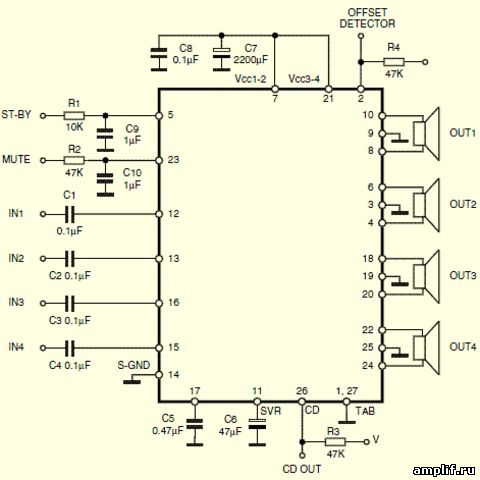
We do not touch the MUTE leg, but connect the ST-BY mode leg through a 10 kilo-ohm resistor to the positive of the general power supply. Now if you apply power to the amplifier (radio tape recorder), it will already be in ready mode.

At the back of the radio there are inputs at which we send a sound signal; the signal can be sent from another radio or, say, from an MP3 player or mobile phone.

We adjust the volume from the device that sent the signal to the radio input.

Ultimately, we get a powerful low-frequency audio amplifier with an excellent design, you can also turn on the radio and listen to the radio, now the processor will not be able to turn off the system at high volumes.
Make your own amplifier from a car radio
For some reasons, many car enthusiasts are in no hurry to get rid of old car radios that have served their purpose. They are not at all embarrassed by the outdated design of this antediluvian device, nor by the fact that its cassette receiver has not been used for its intended purpose for a long time and the equalizer settings are so primitive that the purity of the sound is regulated only by the volume knob of the car radio itself.
In this case, there are only three reasons for the car owner’s enduring love for his “gramophone”:
- Sentimentality;
- Deafness;
- The price of a new and good car radio is a significant part of the cost of the car itself.
Since purely medical workers are competent in the first two reasons, I propose to consider the third option, which contains real instructions on how to make a sound amplifier with your own hands from a car radio that you were about to throw away.
Car radio resuscitation - Method one
So, in order to make an amplifier out of a car radio, we need to ask ourselves the last two control questions:
- Am I satisfied (if I have a conscience and want to ask my passengers) with the output power and “cavity” of the radio?
- Is the sensitivity of the FM tuner sufficient?
If in both cases you put “pluses”, then you can be congratulated, you have just appreciated the internal contents of this music box, namely:
- Digital tuner;
- Sound control unit;
- Stereo - Quad amplifier.
Well, now let's get to the fun part - how to make an amplifier from a car radio?
In solving this dilemma, thanks to modern technologies and technical characteristics of the old, but necessary, head unit, we will significantly facilitate our task by connecting a digital sound source to the old radio. Well, here we have several options to choose from.
If your radio is really old, then this means that it does not have such currently needed outputs as AUX-IN and a USB port. For this we can use the Car Cassette Tape Adapter Transmitter for MP3.
As you can see in the photo, this adapter is made technically and visually as an analogue of a regular cassette - 100.5 * 63.8-12.0 millimeters. I agree, when you saw this device for the first time, at least you had a slight feeling of surprise and a smile, but wait and judge, you will now understand all the charm and genius of this device.
The principle of turning on this adapter is that you insert it like a regular cassette into the “deck” of a car radio, its head is in contact with the head of the player and by connecting a sound source (player, TV - smartphone, laptop, etc.) via a mini-jack, we We get pretty good sound from the speakers, at least better than some FM transmitters.
In general, everyone is happy - we saved a decent amount on purchasing a car radio (see), the tape recorder thinks it is playing a real cassette)))
Advantages
This:
- The idea itself;
- Price;
- Not bad sound;
- It does not pretend to be a cigarette lighter socket, which, you see, is very important!
Flaws
- Unreliable layout (if you do not use a hammer and screwdriver and do not pull the cable, it will last long enough);
- Another protruding cable!!!
- When playing, you can hear the sound of a running tape mechanism (this can be eliminated either by turning up the volume or turning off the mechanism itself).
Method two
If the cassette tray in your car radio is faulty or missing (do such things really exist?), the FM transmitter mentioned above may well become an alternative sound source.
For its full operation, you will need to insert a flash drive with music files through the USB port or connect another sound source via AUX-IN, then make room for it in the cigarette lighter and tune your car radio to the same frequency as the FM transmitter.
Advantages
- Easy to connect and use;
- Extensive possibilities for connecting various sources with music files.
Flaws
- Constantly occupied standard port for powering the cigarette lighter;
- If the performance is poor, there is extraneous noise and periodic “glitches”.
Method three
In this method, I would also like to talk about one option, how to make an amplifier from a car radio for more modern devices, such as smartphones, tablets, laptops and the like with Bluetooth adapters.
In this case, the WirelessBluetoothMusicReceiver adapter will help us out, as long as your head unit has an AUX-IN port. Otherwise, you can always use other adapters, adapters and FM modulators capable of simulating additional stereo audio inputs of an audio power amplifier.
Well, if you consider yourself to be one of the normal guys who are not afraid of difficulties and always take a detour, then I can offer you an option not for the lazy in the following method.
Method four
If you are reading this option on how to make an amplifier from a car radio, then by default I assume that you are at least capable of:
- Hold on to the soldering iron;
- Look at the circuit diagram;
- See familiar letters in the documentation accompanying the car radio.
Attention!
At a minimum, you need to realize that all actions occur at your own peril and risk, and also that you should have an idea of at least the basics of electronics theory. Any “tuning” of the insides of a car radio must be done by you in a sober mind and in good memory)))
- We remove the “old lady” from its standard location and disconnect all connectors and wires:
Advice! All subsequent actions are not for “fussing around on your knees”; you need to settle down in normal conditions.
- By dismantling the top cover, we can observe the cassette unit. We are making the very first modernization - we remove interference and noise of electromagnetic origin created by the electric motor of the tape drive, for which we unsolder the positive wire and insulate it.
It’s not worth tearing it out, what if someone wants to return everything back?
We determine the place where we will solder the AUX-IN output:
- Firstly. We inspect the wires coming from the pickup head; as a rule, they are soldered to the pre-amplifier circuit; you should not solder here;
- Secondly. We find out where the amplified signal comes from pre-amplification, and it goes to the camparator (the microcircuit responsible for switching between the cassette unit and the FM tuner);
- Third. Either by turning on the logic or using the Datasheet (technical documentation) of the preamplifier chip, we find the output of the audio tracks from it. In the case in the photo, these turned out to be heels numbered FPM 1558 and FPM.
Having traced these tracks that connect the output of the pre-amplifier with the comparator signal, we find out where the left and right audio channels are located - by touching the heels of one of the channels with a screwdriver, while an empty audio cassette is turned on, a characteristic crackling sound will be heard in the speakers. Solder the audio cable outputs from AUX-IN to the left (InLeft) and right (InRight) channels. The third pin (InGND) is soldered to the ground (body) of the car radio.
Unfortunately, this instruction cannot contain all the options for soldering the AUX-IN output to the circuits of all kinds of car radios, but I hope you still understand the principle. Moreover, the Internet is full of various videos on this topic.
I propose to stop here, since this topic can go on and on. As they say, there is no limit to perfection, there is only the limit of the imagination of an individual.
Currently, a wide range of imported integrated low-frequency amplifiers has become available. Their advantages are satisfactory electrical parameters, the ability to select microcircuits with a given output power and supply voltage, stereophonic or quadraphonic design with the possibility of bridge connection.
To manufacture a structure based on an integral ULF, a minimum of attached parts is required. The use of known-good components ensures high repeatability and, as a rule, no additional tuning is required.
The given typical switching circuits and main parameters of integrated ULFs are designed to facilitate the orientation and selection of the most suitable microcircuit.
For quadraphonic ULFs, the parameters in bridged stereo are not specified.
TDA1010
Supply voltage - 6...24 V
Output power (Un =14.4 V, THD = 10%):
RL=2 Ohm - 6.4 W
RL=4 Ohm - 6.2 W
RL=8 Ohm - 3.4 W
Quiescent current - 31 mA
Connection diagram
TDA1011
Supply voltage - 5.4...20 V
Maximum current consumption - 3 A
Un=16V - 6.5 W
Un=12V - 4.2 W
Un=9V - 2.3 W
Un=6B - 1.0 W
SOI (P=1 W, RL=4 Ohm) - 0.2%
Quiescent current - 14 mA
Connection diagram
TDA1013
Supply voltage - 10...40 V
Output power (THD=10%) - 4.2 W
THD (P=2.5 W, RL=8 Ohm) - 0.15%
Connection diagram
TDA1015
Supply voltage - 3.6...18 V
Output power (RL=4 Ohm, THD=10%):
Un=12V - 4.2 W
Un=9V - 2.3 W
Un=6B - 1.0 W
SOI (P=1 W, RL=4 Ohm) - 0.3%
Quiescent current - 14 mA
Connection diagram
TDA1020
Supply voltage - 6...18 V
RL=2 Ohm - 12 W
RL=4 Ohm - 7 W
RL=8 Ohm - 3.5 W
Quiescent current - 30 mA
Connection diagram
TDA1510
Supply voltage - 6...18 V
Maximum current consumption - 4 A
THD=0.5% - 5.5 W
THD=10% - 7.0 W
Quiescent current - 120 mA
Connection diagram
TDA1514
Supply voltage - ±10...±30 V
Maximum current consumption - 6.4 A
Output power:
Un =±27.5 V, R=8 Ohm - 40 W
Un =±23 V, R=4 Ohm - 48 W
Quiescent current - 56 mA
Connection diagram
TDA1515
Supply voltage - 6...18 V
Maximum current consumption - 4 A
RL=2 Ohm - 9 W
RL=4 Ohm - 5.5 W
RL=2 Ohm - 12 W
RL4 Ohm - 7 W
Quiescent current - 75 mA
Connection diagram
TDA1516
Supply voltage - 6...18 V
Maximum current consumption - 4 A
Output power (Un =14.4 V, THD = 0.5%):
RL=2 Ohm - 7.5 W
RL=4 Ohm - 5 W
Output power (Un =14.4 V, THD = 10%):
RL=2 Ohm - 11 W
RL=4 Ohm - 6 W
Quiescent current - 30 mA
Connection diagram
TDA1517
Supply voltage - 6...18 V
Maximum current consumption - 2.5 A
Output power (Un=14.4B RL=4 Ohm):
THD=0.5% - 5 W
THD=10% - 6 W
Quiescent current - 80 mA
Connection diagram
TDA1518
Supply voltage - 6...18 V
Maximum current consumption - 4 A
Output power (Un =14.4 V, THD = 0.5%):
RL=2 Ohm - 8.5 W
RL=4 Ohm - 5 W
Output power (Un =14.4 V, THD = 10%):
RL=2 Ohm - 11 W
RL=4 Ohm - 6 W
Quiescent current - 30 mA
Connection diagram
TDA1519
Supply voltage - 6...17.5 V
Maximum current consumption - 4 A
Output power (Up=14.4 V, THD=0.5%):
RL=2 Ohm - 6 W
RL=4 Ohm - 5 W
Output power (Un =14.4 V, THD = 10%):
RL=2 Ohm - 11 W
RL=4 Ohm - 8.5 W
Quiescent current - 80 mA
Connection diagram
TDA1551
Supply voltage -6...18 V
THD=0.5% - 5 W
THD=10% - 6 W
Quiescent current - 160 mA
Connection diagram
TDA1521
Supply voltage - ±7.5...±21 V
Output power (Un=±12 V, RL=8 Ohm):
THD=0.5% - 6 W
THD=10% - 8 W
Quiescent current - 70 mA
Connection diagram
TDA1552
Supply voltage - 6...18 V
Maximum current consumption - 4 A
Output power (Un =14.4 V, RL = 4 Ohm):
THD=0.5% - 17 W
THD=10% - 22 W
Quiescent current - 160 mA
Connection diagram
TDA1553
Supply voltage - 6...18 V
Maximum current consumption - 4 A
Output power (Up=4.4 V, RL=4 Ohm):
THD=0.5% - 17 W
THD=10% - 22 W
Quiescent current - 160 mA
Connection diagram
TDA1554
Supply voltage - 6...18 V
Maximum current consumption - 4 A
THD=0.5% - 5 W
THD=10% - 6 W
Quiescent current - 160 mA
Connection diagram
TDA2004
Output power (Un=14.4 V, THD=10%):
RL=4 Ohm - 6.5 W
RL=3.2 Ohm - 8.0 W
RL=2 Ohm - 10 W
RL=1.6 Ohm - 11 W
KHI (Un=14.4V, P=4.0 W, RL=4 Ohm) - 0.2%;
Bandwidth (at -3 dB level) - 35...15000 Hz
Quiescent current -<120 мА
Connection diagram
TDA2005
Dual integrated ULF, designed specifically for use in cars and allowing operation with low-impedance loads (up to 1.6 Ohms).
Supply voltage - 8...18 V
Maximum current consumption - 3.5 A
Output power (Up = 14.4 V, THD = 10%):
RL=4 Ohm - 20 W
RL=3.2 Ohm - 22 W
SOI (Uп =14.4 V, Р=15 W, RL=4 Ohm) - 10%
Bandwidth (level -3 dB) - 40...20000 Hz
Quiescent current -<160 мА
Connection diagram
TDA2006
The pin layout matches the pin layout of the TDA2030 chip.
Supply voltage - ±6.0...±15 V
Maximum current consumption - 3 A
Output power (Ep=±12V, THD=10%):
at RL=4 Ohm - 12 W
at RL=8 Ohm - 6...8 W THD (Ep=±12V):
at P=8 W, RL= 4 Ohm - 0.2%
at P=4 W, RL= 8 Ohm - 0.1%
Bandwidth (at -3 dB level) - 20...100000 Hz
Consumption current:
at P=12 W, RL=4 Ohm - 850 mA
at P=8 W, RL=8 Ohm - 500 mA
Connection diagram
TDA2007
Dual integrated ULF with single-row pin arrangement, specially designed for use in television and portable radio receivers.
Supply voltage - +6...+26 V
Quiescent current (Ep=+18 V) - 50...90 mA
Output power (THD=0.5%):
at Ep=+18 V, RL=4 Ohm - 6 W
at Ep=+22 V, RL=8 Ohm - 8 W
SOI:
at Ep=+18 V P=3 W, RL=4 Ohm - 0.1%
at Ep=+22 V, P=3 W, RL=8 Ohm - 0.05%
Bandwidth (at -3 dB level) - 40...80000 Hz
Connection diagram
TDA2008
Integrated ULF, designed to operate on low-impedance loads, providing high output current, very low harmonic content and intermodulation distortion.
Supply voltage - +10...+28 V
Quiescent current (Ep=+18 V) - 65...115 mA
Output power (Ep=+18V, THD=10%):
at RL=4 Ohm - 10...12 W
at RL=8 Ohm - 8 W
SOI (Ep= +18 V):
at P=6 W, RL=4 Ohm - 1%
at P=4 W, RL=8 Ohm - 1%
Maximum current consumption - 3 A
Connection diagram
TDA2009
Dual integrated ULF, designed for use in high-quality music centers.
Supply voltage - +8...+28 V
Quiescent current (Ep=+18 V) - 60...120 mA
Output power (Ep=+24 V, THD=1%):
at RL=4 Ohm - 12.5 W
at RL=8 Ohm - 7 W
Output power (Ep=+18 V, THD=1%):
at RL=4 Ohm - 7 W
at RL=8 Ohm - 4 W
SOI:
at Ep= +24 V, P=7 W, RL=4 Ohm - 0.2%
at Ep= +24 V, P=3.5 W, RL=8 Ohm - 0.1%
at Ep= +18 V, P=5 W, RL=4 Ohm - 0.2%
at Ep= +18 V, P=2.5 W, RL=8 Ohm - 0.1%
Maximum current consumption - 3.5 A
Connection diagram
TDA2030
Integrated ULF, providing high output current, low harmonic content and intermodulation distortion.
Supply voltage - ±6...±18 V
Quiescent current (Ep=±14 V) - 40...60 mA
Output power (Ep=±14 V, THD = 0.5%):
at RL=4 Ohm - 12...14 W
at RL=8 Ohm - 8...9 W
SOI (Ep=±12V):
at P=12 W, RL=4 Ohm - 0.5%
at P=8 W, RL=8 Ohm - 0.5%
Bandwidth (at -3 dB level) - 10...140000 Hz
Consumption current:
at P=14 W, RL=4 Ohm - 900 mA
at P=8 W, RL=8 Ohm - 500 mA
Connection diagram
TDA2040
Integrated ULF, providing high output current, low harmonic content and intermodulation distortion.
Supply voltage - ±2.5...±20 V
Quiescent current (Ep=±4.5...±14 V) - mA 30...100 mA
Output power (Ep=±16 V, THD = 0.5%):
at RL=4 Ohm - 20...22 W
at RL=8 Ohm - 12 W
THD (Ep=±12V, P=10 W, RL = 4 Ohm) - 0.08%
Maximum current consumption - 4 A
Connection diagram
TDA2050
Integrated ULF, providing high output power, low harmonic content and intermodulation distortion. Designed to work in Hi-Fi stereo systems and high-end TVs.
Supply voltage - ±4.5...±25 V
Quiescent current (Ep=±4.5...±25 V) - 30...90 mA
Output power (Ep=±18, RL = 4 Ohm, THD = 0.5%) - 24...28 W
SOI (Ep=±18V, P=24Wt, RL=4 Ohm) - 0.03...0.5%
Bandwidth (at -3 dB level) - 20...80000 Hz
Maximum current consumption - 5 A
Connection diagram
TDA2051
Integrated ULF, which has a small number of external elements and provides low harmonic content and intermodulation distortion. The output stage operates in class AB, which allows for greater output power.
Output power:
at Ep=±18 V, RL=4 Ohm, THD=10% - 40 W
at Ep=±22 V, RL=8 Ohm, THD=10% - 33 W
Connection diagram
TDA2052
Integrated ULF, the output stage of which operates in class AB. Accepts a wide range of supply voltages and has a high output current. Designed for use in television and radio receivers.
Supply voltage - ±6...±25 V
Quiescent current (En = ±22 V) - 70 mA
Output power (Ep = ±22 V, THD = 10%):
at RL=8 Ohm - 22 W
at RL=4 Ohm - 40 W
Output power (En = 22 V, THD = 1%):
at RL=8 Ohm - 17 W
at RL=4 Ohm - 32 W
SOI (with a passband at the level of -3 dB 100... 15000 Hz and Pout = 0.1... 20 W):
at RL=4 Ohm -<0,7 %
at RL=8 Ohm -<0,5 %
Connection diagram
TDA2611
Integrated ULF designed for use in household equipment.
Supply voltage - 6...35 V
Quiescent current (Ep=18 V) - 25 mA
Maximum current consumption - 1.5 A
Output power (THD=10%): at Ep=18 V, RL=8 Ohm - 4 W
at Ep=12V, RL=8 0m - 1.7 W
at Ep=8.3 V, RL=8 Ohm - 0.65 W
at Ep=20 V, RL=8 Ohm - 6 W
at Ep=25 V, RL=15 Ohm - 5 W
THD (at Pout=2 W) - 1%
Bandwidth - >15 kHz
Connection diagram
TDA2613
SOI:
(Ep=24 V, RL=8 Ohm, Pout=6 W) - 0.5%
(En=24 V, RL=8 Ohm, Pout=8 W) - 10%
Quiescent current (Ep=24 V) - 35 mA
Connection diagram
TDA2614
Integrated ULF, designed for use in household equipment (television and radio receivers).
Supply voltage - 15...42 V
Maximum current consumption - 2.2 A
Quiescent current (Ep=24 V) - 35 mA
SOI:
(Ep=24 V, RL=8 Ohm, Pout=6.5 W) - 0.5%
(Ep=24 V, RL=8 Ohm, Pout=8.5 W) - 10%
Bandwidth (level -3 dB) - 30...20000 Hz
Connection diagram
TDA2615
Dual ULF, designed for use in stereo radios or televisions.
Supply voltage - ±7.5...21 V
Maximum current consumption - 2.2 A
Quiescent current (Ep=7.5...21 V) - 18...70 mA
Output power (Ep=±12 V, RL=8 Ohm):
THD=0.5% - 6 W
THD=10% - 8 W
Bandwidth (at level -3 dB and Pout = 4 W) - 20...20000 Hz
Connection diagram
TDA2822
Dual ULF, designed for use in portable radios and television receivers.
Quiescent current (Ep=6 V) - 12 mA
Output power (THD=10%, RL=4 Ohm):
Ep=9V - 1.7 W
Ep=6V - 0.65 W
Ep=4.5V - 0.32 W
Connection diagram
TDA7052
ULF designed for use in battery-powered wearable audio devices.
Supply voltage - 3...15V
Maximum current consumption - 1.5A
Quiescent current (E p = 6 V) -<8мА
Output power (Ep = 6 V, R L = 8 Ohm, THD = 10%) - 1.2 W
Connection diagram
TDA7053
Dual ULF designed for use in wearable audio devices, but can also be used in any other equipment.
Supply voltage - 6...18 V
Maximum current consumption - 1.5 A
Quiescent current (E p = 6 V, R L = 8 Ohm) -<16 mA
Output power (E p = 6 V, RL = 8 Ohm, THD = 10%) - 1.2 W
SOI (E p = 9 V, R L = 8 Ohm, Pout = 0.1 W) - 0.2%
Operating frequency range - 20...20000 Hz
Connection diagram
TDA2824
Dual ULF designed for use in portable radio and television receivers
Supply voltage - 3...15 V
Maximum current consumption - 1.5 A
Quiescent current (Ep=6 V) - 12 mA
Output power (THD=10%, RL=4 Ohm)
Ep=9 V - 1.7 W
Ep=6 V - 0.65 W
Ep=4.5 V - 0.32 W
THD (Ep=9 V, RL=8 Ohm, Pout=0.5 W) - 0.2%
Connection diagram
TDA7231
ULF with a wide range of supply voltages, designed for use in portable radios, cassette recorders, etc.
Supply voltage - 1.8...16 V
Quiescent current (Ep=6 V) - 9 mA
Output power (THD=10%):
En=12B, RL=6 Ohm - 1.8 W
En=9B, RL=4 Ohm - 1.6 W
Ep=6 V, RL=8 Ohm - 0.4 W
Ep=6 V, RL=4 Ohm - 0.7 W
Ep=3 V, RL=4 Ohm - 0.11 W
Ep=3 V, RL=8 Ohm - 0.07 W
THD (Ep=6 V, RL=8 Ohm, Pout=0.2 W) - 0.3%
Connection diagram
TDA7235
ULF with a wide range of supply voltages, designed for use in portable radio and television receivers, cassette recorders, etc.
Supply voltage - 1.8...24 V
Maximum current consumption - 1.0 A
Quiescent current (Ep=12 V) - 10 mA
Output power (THD=10%):
Ep=9 V, RL=4 Ohm - 1.6 W
Ep=12 V, RL=8 Ohm - 1.8 W
Ep=15 V, RL=16 Ohm - 1.8 W
Ep=20 V, RL=32 Ohm - 1.6 W
THD (Ep=12V, RL=8 Ohm, Pout=0.5 W) - 1.0%
Connection diagram
TDA7240
Quiescent current (Ep=14.4 V) - 120 mA
RL=4 Ohm - 20 W
RL=8 Ohm - 12 W
SOI:
(Ep=14.4 V, RL=8 Ohm, Pout=12W) - 0.05%
Connection diagram
TDA7241
Bridged ULF, designed for use in car radios. It has protection against short circuits in the load, as well as overheating.
Maximum supply voltage - 18 V
Maximum current consumption - 4.5 A
Quiescent current (Ep=14.4 V) - 80 mA
Output power (Ep=14.4 V, THD=10%):
RL=2 Ohm - 26 W
RL=4 Ohm - 20 W
RL=8 Ohm - 12 W
SOI:
(Ep=14.4 V, RL=4 Ohm, Pout=12 W) - 0.1%
(Ep=14.4 V, RL=8 Ohm, Pout=6 W) - 0.05%
Bandwidth level -3 dB (RL=4 Ohm, Pout=15 W) - 30...25000 Hz
Connection diagram
TDA1555Q
Supply voltage - 6...18 V
Maximum current consumption - 4 A
Output power (Up = 14.4 V. RL = 4 Ohm):
- THD=0.5% - 5 W
- THD=10% - 6 W Quiescent current - 160 mA
Connection diagram
TDA1557Q
Supply voltage - 6...18 V
Maximum current consumption - 4 A
Output power (Up = 14.4 V, RL = 4 Ohm):
- THD=0.5% - 17 W
- THD=10% - 22 W
Quiescent current, mA 80
Connection diagram
TDA1556Q
Supply voltage -6...18 V
Maximum current consumption -4 A
Output power: (Up=14.4 V, RL=4 Ohm):
- THD=0.5%, - 17 W
- THD=10% - 22 W
Quiescent current - 160 mA
Connection diagram
TDA1558Q
Supply voltage - 6..18 V
Maximum current consumption - 4 A
Output power (Up=14 V, RL=4 Ohm):
- THD=0.6% - 5 W
- THD=10% - 6 W
Quiescent current - 80 mA
Connection diagram
TDA1561
Supply voltage - 6...18 V
Maximum current consumption - 4 A
Output power (Up=14V, RL=4 Ohm):
- THD=0.5% - 18 W
- THD=10% - 23 W
Quiescent current - 150 mA
Connection diagram
TDA1904
Supply voltage - 4...20 V
Maximum current consumption - 2 A
Output power (RL=4 Ohm, THD=10%):
- Up=14 V - 4 W
- Up=12V - 3.1 W
- Up=9 V - 1.8 W
- Up=6 V - 0.7 W
SOI (Up=9 V, P<1,2 Вт, RL=4 Ом) - 0,3 %
Quiescent current - 8...18 mA
Connection diagram
TDA1905
Supply voltage - 4...30 V
Maximum current consumption - 2.5 A
Output power (THD=10%)
- Up=24 V (RL=16 Ohm) - 5.3 W
- Up=18V (RL=8 Ohm) - 5.5 W
- Up=14 V (RL=4 Ohm) - 5.5 W
- Up=9 V (RL=4 Ohm) - 2.5 W
SOI (Up=14 V, P<3,0 Вт, RL=4 Ом) - 0,1 %
Quiescent current -<35 мА
Connection diagram
TDA1910
Supply voltage - 8...30 V
Maximum current consumption - 3 A
Output power (THD=10%):
- Up=24 V (RL=8 Ohm) - 10 W
- Up=24 V (RL=4 Ohm) - 17.5 W
- Up=18 V (RL=4 Ohm) - 9.5 W
SOI (Up=24 V, P<10,0 Вт, RL=4 Ом) - 0,2 %
Quiescent current -<35 мА
Connection diagram
TDA2003
Supply voltage - 8...18 V
Maximum current consumption - 3.5 A
Output power (Up=14V, THD=10%):
- RL=4.0 Ohm - 6 W
- RL=3.2 Ohm - 7.5 W
- RL=2.0 Ohm - 10 W
- RL=1.6 Ohm - 12 W
SOI (Up=14.4 V, P<4,5 Вт, RL=4 Ом) - 0,15 %
Quiescent current -<50 мА
Connection diagram
TDA7056
ULF designed for use in portable radio and television receivers.
Supply voltage - 4.5...16 V Maximum current consumption - 1.5 A
Quiescent current (E p = 12 V, R = 16 Ohm) -<16 мА
Output power (E P = 12 V, R L = 16 Ohm, THD = 10%) - 3.4 W
THD (E P = 12 V, R L = 16 Ohm, Pout = 0.5 W) - 1%
Operating frequency range - 20...20000 Hz
Connection diagram
TDA7245
ULF designed for use in wearable audio devices, but can also be used in any other equipment.Supply voltage - 12...30 V
Maximum current consumption - 3.0 A
Quiescent current (E p = 28 V) -<35 мА
Output power (THD = 1%):
-E p = 14 V, R L = 4 Ohm - 4 W
-E P = 18 V, R L = 8 Ohm - 4 W
Output power (THD = 10%):
-E P = 14 V, R L = 4 Ohm - 5 W
-E P = 18 V, R L = 8 Ohm - 5 W
SOI,%
-E P = 14 V, R L = 4 Ohm, Pout<3,0 - 0,5 Вт
-E P = 18 V, R L = 8 Ohm, Pout<3,5 - 0,5 Вт
-E P = 22 V, RL = 16 Ohm, Pout<3,0 - 0.4 Вт
Bandwidth by level
-ZdB(E =14 V, PL = 4 Ohm, Pout = 1 W) - 50...40000 Hz
TEA0675
Two-channel Dolby B noise suppressor designed for automotive applications. Contains pre-amplifiers, an electronically controlled equalizer, and an electronic pause detection device for the Automatic Music Search (AMS) scanning mode. Structurally, it is carried out in SDIP24 and SO24 housings.Supply voltage, 7.6,..12 V
Current consumption, 26...31 mA
Ratio (signal+noise)/signal, 78...84 dB
Harmonic distortion factor:
at a frequency of 1 kHz, 0.08...0.15%
at a frequency of 10 kHz, 0.15...0.3%
Output impedance, 10 kOhm
Voltage gain, 29...31 dB
TEA0678
Two-channel integrated Dolby B noise suppressor designed for use in car audio equipment. Includes pre-amplifier stages, electronically controlled equalizer, electronic signal source switcher, Automatic Music Search (AMS) system.Available in SDIP32 and SO32 packages.
Current consumption, 28 mA
Preamp gain (at 1 kHz), 31 dB
Harmonic distortion
< 0,15 %
at a frequency of 1 kHz at Uout=6 dB,< 0,3 %
Noise voltage, normalized to the input, in the frequency range 20...20000 Hz at Rist=0, 1.4 µV
TEA0679
Two-channel integrated amplifier with Dolby B noise reduction system, designed for use in various car audio equipment. Includes pre-amplification stages, an electronically controlled equalizer, an electronic signal source switch, and an Automatic Music Search (AMS) system. The main IC adjustments are controlled via the I2C busAvailable in SO32 housing.
Supply voltage, 7.6...12 V
Current consumption, 40 mA
Harmonic distortion
at a frequency of 1 kHz at Uout=0 dB,< 0,15 %
at a frequency of 1 kHz at Uout=10 dB,< 0,3 %
Crosstalk attenuation between channels (Uout=10 dB, at a frequency of 1 kHz), 63 dB
Signal+noise/noise ratio, 84 dB
TDA0677
Dual pre-amplifier-equalizer designed for use in car radios. Includes a preamplifier and a corrector amplifier with an electronic time constant switch. Also contains an electronic input switch.The IC is manufactured in the SOT137A package.
Supply voltage, 7.6.,.12 V
Current consumption, 23...26 mA
Signal+noise/noise ratio, 68...74 dB
Harmonic distortion:
at a frequency of 1 kHz at Uout = 0 dB, 0.04...0.1%
at a frequency of 10 kHz at Uout = 6 dB, 0.08...0.15%
Output impedance, 80... 100 Ohm
Gain:
at a frequency of 400 Hz, 104...110 dB
at a frequency of 10 kHz, 80..86 dB
TEA6360
Two-channel five-band equalizer, controlled via 12C bus, designed for use in car radios, televisions, and music centers.Manufactured in SOT232 and SOT238 packages.
Supply voltage, 7... 13.2 V
Current consumption, 24.5 mA
Input voltage, 2.1 V
Output voltage, 1 V
Reproducible frequency range at level -1dB, 0...20000 Hz
Nonlinear distortion coefficient in the frequency range 20...12500 Hz and output voltage 1.1 V, 0.2...0.5%
Transfer coefficient, 0.5...0 dB
Operating temperature range, -40...+80 C
TDA1074A
Designed for use in stereo amplifiers as a two-channel tone control (low and mid frequencies) and sound. The chip includes two pairs of electronic potentiometers with eight inputs and four separate output amplifiers. Each potentiometric pair is adjusted individually by applying constant voltage to the corresponding terminals.The IC is manufactured in SOT102, SOT102-1 packages.
Maximum supply voltage, 23 V
Current consumption (no load), 14...30 mA
Gain, 0 dB
Harmonic distortion:
at a frequency of 1 kHz at Uout = 30 mV, 0.002%
at a frequency of 1 kHz at Uout = 5 V, 0.015...1%
Output noise voltage in the frequency range 20...20000 Hz, 75 μV
Interchannel isolation in the frequency range 20...20000 Hz, 80 dB
Maximum power dissipation, 800 mW
Operating temperature range, -30...+80°С
TEA5710
A functionally complete IC that performs the functions of an AM and FM receiver. Contains all the necessary stages: from a high-frequency amplifier to an AM/FM detector and a low-frequency amplifier. It is characterized by high sensitivity and low current consumption. Used in portable AM/FM receivers, radio timers, radio headphones. The IC is manufactured in the SOT234AG (SOT137A) package.Supply voltage, 2..,12 V
Consumption current:
in AM mode, 5.6...9.9 mA
in FM mode, 7.3...11.2 mA
Sensitivity:
in AM mode, 1.6 mV/m
in FM mode at signal-to-noise ratio 26 dB, 2.0 µV
Harmonic distortion:
in AM mode, 0.8..2.0%
in FM mode, 0.3...0.8%
Low frequency output voltage, 36...70 mV